Liquid medium deceleration strip

A technology of liquid medium and speed bumps, applied in the directions of roads, road signs, traffic signals, etc., can solve the problems of large damage to the road surface, noise, bumpy feeling, etc., to ensure the basic functions and reduce the difficulty of construction.

Inactive Publication Date: 2018-02-23
卢建璋
View PDF6 Cites 4 Cited by
  • Summary
  • Abstract
  • Description
  • Claims
  • Application Information

AI Technical Summary

Problems solved by technology

[0003] The purpose of the present invention is to propose a liquid medium deceleration belt to solve the problems of noise generation, bumpy feeling and large damage to the road surface in the prior art

Method used


Image

  • Liquid medium deceleration strip
  • Liquid medium deceleration strip
  • Liquid medium deceleration strip

Examples


Embodiment 1

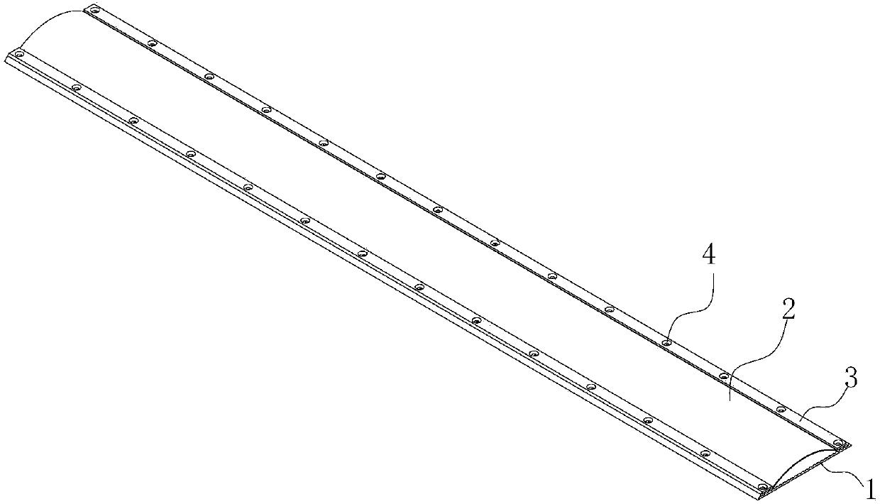
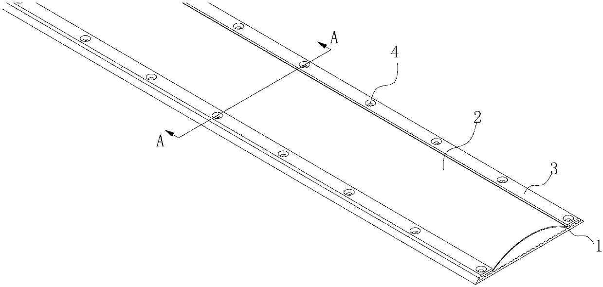
[0025] See attached figure 1 - attached Figure 6 , a liquid medium speed bump of the present invention includes:

[0026] bottom plate 1;

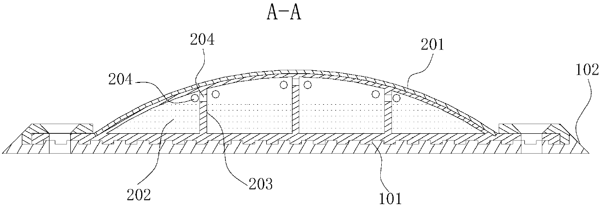
[0027] The inside of the base plate 1 is a hollow deceleration body 2, and the interior of the deceleration body 2 is intersected with a plurality of transverse isolation strips 202 and a plurality of longitudinal isolation strips 203 to form a plurality of cavities. Each transverse isolation strip 202 and A plurality of overflow holes 204 are evenly arranged on the upper part of each longitudinal isolation belt 203, so that two adjacent cavities are connected, and liquid is arranged in the cavity, and the overflow holes 204 ensure the flow of liquid in the two adjacent cavities , the distance between two adjacent lateral isolation belts 202 is a wheel width, ensuring that the liquid in the cavity corresponding to the pressurized position can flow into the adjacent cavity;

[0028] As well as the pressing plate 3 arranged on both sides...

Embodiment 2

[0037] The difference between this embodiment and Embodiment 1 is that: the liquid is provided in the cavity, specifically: the cavity provided with liquid in the horizontal direction and the cavity without liquid are arranged alternately, the cavity provided with liquid in the vertical direction and the cavity without liquid The cavities are staggered.

[0038] The working principle of this embodiment is: when the wheel is pressed at a low speed, the liquid will be gradually surged forward, and when the height of the overflow hole 204 on the horizontal isolation zone 202 and the longitudinal isolation zone 203 corresponding to the pressurized cavity is lower than that of the liquid When the surface height is high, the liquid will be forced to flow into the front and side cavities from the overflow hole 204 and remain in the adjacent front and side cavities. Pass, when the wheel rolls over other positions again, the same principle is used to achieve deceleration; when the whee...


PUM


Abstract

The invention provides a liquid medium deceleration strip which belongs to the technical field of road traffic construction and aims to solve the problems existing in the prior art that noise is caused, the feeling of bumping exists, and the degree of damage to a road surface is greater. The liquid medium deceleration strip comprises a bottom plate, a deceleration body and pressing plates, whereinthe hollow is arranged on the bottom plate; a plurality of transverse isolation strips and a plurality of longitudinal isolation strips are arranged in the deceleration body in a crossing manner to form a plurality of cavities; a plurality of overflow holes are uniformly formed in each of the upper parts of each of the transverse isolation strips and each of the longitudinal isolation strips; liquid is put into the cavities; the pressing plates are arranged on the two sides of the upper surface of the bottom plate; a plurality of self-tapping screw that are arranged uniformly penetrate through the pressing plates, the deceleration body and the bottom plate in sequence and are fixed with ground. In the liquid medium deceleration strip, a form of cavity rubber filled with a liquid medium isadopted, and the principle of the relationship of the running speed of wheels and the time that liquid flows out of the cavities is utilized, so that the arching degree of the deceleration strip is controlled; the basic function of the deceleration strip is ensured, the comfortability at low speed is improved, and the noise is reduced; the degree of damage to a road surface is reduced.

Description

technical field [0001] The invention belongs to the technical field of road traffic construction, and in particular relates to a liquid-medium deceleration belt that utilizes flowing liquid to buffer and realize deceleration. Background technique [0002] Speed ​​bumps are traffic facilities installed on roads to slow down passing vehicles. The speed bump makes the road surface arch upwards to force the vehicle to slow down. It is generally set at highway crossings, industrial and mining enterprises, schools, residential quarter entrances and other road sections that require vehicles to slow down and road sections that are prone to traffic accidents. It is used to slow down motor vehicles. , New traffic-specific safety settings for the speed of non-motorized vehicles. The speed reduction belt realizes deceleration by affecting the driver's driving psychology, even forcing the driver to slow down by reducing the comfort and safety of the vehicle. In the prior art, speed bum...

Claims


Application Information

Patent Timeline
Patent Type & Authority Applications(China)
IPC IPC(8): E01F9/529
CPCE01F9/529
Inventor 卢建璋翟麒凯欧心旸刘轩赫
Owner 卢建璋
Why Eureka
Try Eureka