Air pipe and draught fan

An air duct and fan technology, applied in mechanical equipment, machines/engines, liquid fuel engines, etc., can solve the problems of uneven distribution of gas mass flow, reduce the efficiency of centrifugal fans, increase energy loss, etc., and achieve uniform distribution of gas mass flow. , The effect of stable flow and reducing flow loss

Inactive Publication Date: 2018-02-23
CHONGQING GENERAL IND (GRP) LTD
View PDF9 Cites 1 Cited by
  • Summary
  • Abstract
  • Description
  • Claims
  • Application Information

AI Technical Summary

Problems solved by technology

[0003] When the air inlet pipes of various existing centrifugal fans divert fluid, the airflow tends to form vortices and secondary flows in the pipes, causing flow turbulence in the pipes, resulting in increased energy loss
At the same time, due to the turbulent flow in the pipe, the gas mass flow distribution is uneven, thereby reducing the efficiency of the centrifugal fan

Method used


Image

  • Air pipe and draught fan
  • Air pipe and draught fan
  • Air pipe and draught fan

Examples


Embodiment

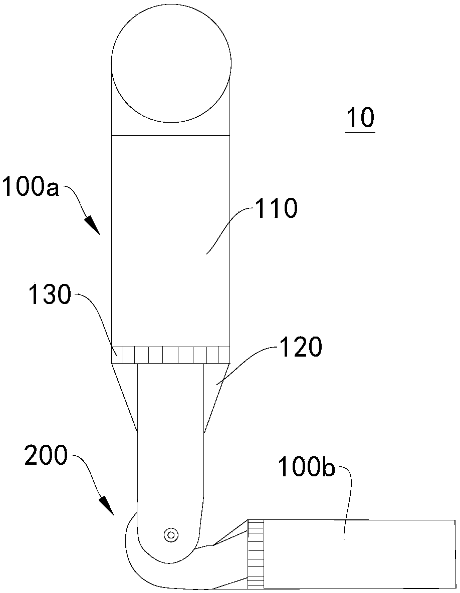
[0039] Please refer to figure 1 This embodiment provides a fan 10, which includes a centrifugal fan 200 and an air duct 100a. The air duct 100a can be connected to the air inlet of the centrifugal fan 200. The air duct 100a can remove fluid (gas) away from the air inlet of the centrifugal fan 200. It is introduced into the centrifugal fan 200, and then the internal impeller of the centrifugal fan 200 does work to deliver the fluid to the target location.

[0040] In detail, the above-mentioned air duct 100a may include a first air inlet pipe 110, a second air inlet pipe 120, and a mesh grille 130. The first air inlet pipe 110 is connected to the second air inlet pipe 120, and the mesh grille 130 may be disposed on the second air inlet pipe. Between an air inlet pipe 110 and a second air inlet pipe 120.

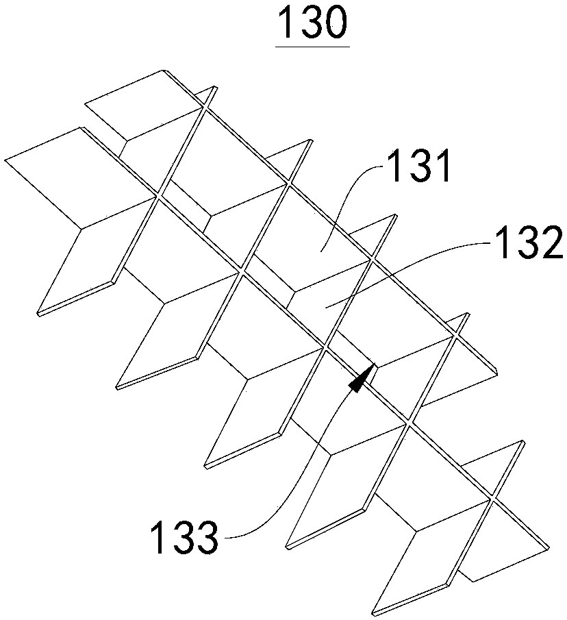
[0041] Further, please refer to figure 2 , The aforementioned mesh grid 130 may include a first partition 131 and a second partition 132, the first partition 131 and the second pa...


PUM


Abstract

The invention relates to the technical field of draught fans, in particular to an air pipe and a draught fan. The draught fan comprises a centrifugal draught fan body and the air pipe. The air pipe comprises a first air inlet pipe body, a second air inlet pipe body and a grid, the first air inlet pipe body is connected to the second air inlet pipe body, the grid is arranged between the first air inlet pipe body and the second air inlet pipe body, the grid comprises first partition plates and second partition plates, and the first partition plates and the second partition plates are arranged ina crossed mode; and eddies generated by a curve in a pipeline and eddies generated in the draught fan are destroyed by utilizing the grid arranged in the air pipe, so that flowing in the pipeline tends to be at a stable state, flowing loss in the pipe is reduced, and therefore mass flow distribution in the pipe body is more even.

Description

Technical field [0001] The present invention relates to the technical field of fans, in particular to air ducts and fans. Background technique [0002] The centrifugal fan system is a fluid conveying system with air as the main medium, which is mainly composed of centrifugal fans and air ducts. The centrifugal fan provides power for the entire conveying system. The function of the air inlet pipe is to introduce the fluid away from the inlet of the fan into the fan, perform work through the impeller inside the fan, and finally guide the fluid to the target point through the exhaust pipe. [0003] When the air inlet pipes of various existing centrifugal fans divert fluid, the airflow is likely to form vortices and secondary flows in the pipes, causing turbulence in the pipes, resulting in an increase in energy loss. At the same time, due to the turbulent flow in the tube, the gas mass flow distribution is uneven, thereby reducing the efficiency of the centrifugal fan. Summary of th...

Claims


Application Information

Patent Timeline
Patent Type & Authority Applications(China)
IPC IPC(8): F04D29/66F04D29/42
CPCF04D29/4226F04D29/667
Inventor 周红黄顺巧满超
Owner CHONGQING GENERAL IND (GRP) LTD
Why Eureka
Try Eureka