
Steady pressure type high-capacity energy accumulator

A large-capacity, accumulator technology, applied in the direction of machinery and equipment, can solve the problems of small internal space, low reliability, large design of fixtures, pumping stations, etc., to save manufacturing costs, simplify the structure, and save operating costs Effect

Active Publication Date: 2018-02-23
张艳东
View PDF7 Cites 0 Cited by
  • Summary
  • Abstract
  • Description
  • Claims
  • Application Information

AI Technical Summary

Problems solved by technology

[0006] 1. Due to the complicated structure of conventional accumulators, especially when the fixture space is small, the size of the accumulator needs to be large, resulting in a very large design of the entire fixture and pumping station, so the manufacturing cost is particularly high and reliable. lower sex
[0007] 2. In the manufacturing process of the accumulator, due to the small internal space, when a large-capacity accumulator is required, the accumulator body is made larger, resulting in a lot of waste of manufacturing costs
[0008] 3. Some parts of the accumulator will age during use, such as the bladder of the bladder accumulator will age, resulting in the phenomenon of bursting and safety accidents

Method used


Image

  • Steady pressure type high-capacity energy accumulator

Examples


Embodiment Construction

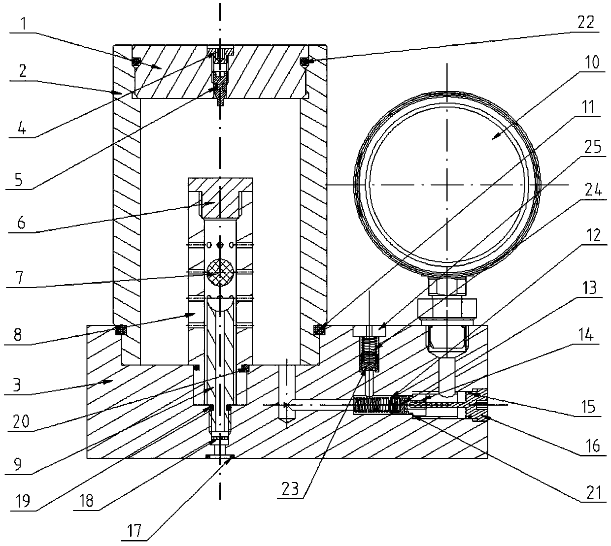
[0029] The present invention will be further described below in conjunction with the accompanying drawings. Such as figure 1 As shown, the pressure-stabilized large-capacity accumulator includes a base 3, a cylinder 2, an upper end cover 1 with an air supply device, and a limit assembly with a function of limiting the height of the oil level. The lower end of the cylinder 2 is installed on the An upper end cover 1 is arranged on the base 3 and its upper end; the upper surface of the base 3, the inner wall surface of the cylinder body 2 and the lower surface of the upper end cover 1 form an energy storage cavity; the upper part of the energy storage cavity is gas, and the lower part is It is hydraulic oil; the limiting assembly is arranged on the base 3 in the energy storage chamber.

[0030] Further, the base 3 is provided with a four-way oil circuit, and the first to fourth branches of the four-way oil circuit communicate with the energy storage chamber, the one-way valve as...


PUM


Abstract

The invention discloses a steady pressure type high-capacity energy accumulator. The steady pressure type high-capacity energy accumulator comprises a base, a cylinder body, an upper end cover provided with an air supplement device, a limiting assembly with a function of limiting the height of a fuel head, a single-way valve assembly with the function of opening a fuel way between a pressure gageand an energy storage cavity, an overflow valve assembly and the pressure gage. The upper surface of the base, the inner wall face of the cylinder body and the lower surface of the upper end cover form the energy storage cavity. The upper portion of the interior of the energy storage cavity is gas, and the lower portion is hydraulic oil. The limiting assembly is arranged on the portion, in the energy storage cavity, of the base. The steady pressure type high-capacity energy accumulator is simple in structure, can effectively utilize the space, reduces the diameter of the cylinder body of the energy accumulator, and simplifies the structural style of a traditional energy accumulator. Compared with an existing energy accumulator with the same capacity, the size of the steady pressure type high-capacity energy accumulator can be reduced by one quarter, thus the production and manufacturing cost is saved, and the reliability of the structure is improved. In the working process of the steady pressure type high-capacity energy accumulator, special hydraulic oil is not needed, therefore waste of the hydraulic oil cannot be generated, and the operation cost is saved. The steady pressure type high-capacity energy accumulator reduces the workload of maintenance in the later period.

Description

technical field [0001] The invention relates to a pressure stabilizing device of a hydraulic system, in particular to a large-capacity accumulator. Background technique [0002] In recent years, industrial systems using hydraulic systems as power transmission systems have become more and more common, and with the rapid development of science and technology, there is an increasing demand for high-pressure hydraulic systems and even ultra-high-pressure hydraulic systems in industrial production, construction machinery and military fields. more urgent. [0003] As an important hydraulic auxiliary component in the hydraulic system, the accumulator plays an important role in storing energy in the hydraulic system. In the hydraulic system, the accumulator plays the role of storing the system pressure oil, which is released for use by the system when needed, so as to achieve the purpose of balancing the hydraulic system and saving energy. Another important function of the accumul...

Claims


Application Information

Patent Timeline
Patent Type & Authority Applications(China)
IPC IPC(8): F15B1/04
CPCF15B1/04Y02E60/16
Inventor 不公告发明人
Owner 张艳东
Learn More