Supercharge Your Innovation With Domain-Expert AI Agents!

Oil-gas separation device and method of hot oil circulation system

A separation device and circulation system technology, applied in the boiler field, can solve problems such as easy generation of air bubbles, unused heat, and influence on combustion effect, and achieve the effects of blocking sediment, simple structure, and improving energy utilization rate

Inactive Publication Date: 2018-02-23
崔小勤
View PDF0 Cites 6 Cited by
  • Summary
  • Abstract
  • Description
  • Claims
  • Application Information

AI Technical Summary

Problems solved by technology

[0002] The gas-fired hot oil boiler uses heat-conducting oil as the medium, and uses the hot oil circulating oil pump to force the medium to circulate in liquid phase, and then transfers the heat energy to the heat-consuming equipment and then returns to the heating furnace for reheating. , Air bubbles are easy to form in the pipeline. If the bubbles are not overflowed in time, the pressure in the pipeline will increase and the equipment will be damaged. There is still a lot of heat in the flue gas discharged from the boiler, which is not used

Method used


Image

  • Oil-gas separation device and method of hot oil circulation system
  • Oil-gas separation device and method of hot oil circulation system
  • Oil-gas separation device and method of hot oil circulation system

Examples


Embodiment Construction

[0028] The present invention will be further described below in conjunction with the accompanying drawings.

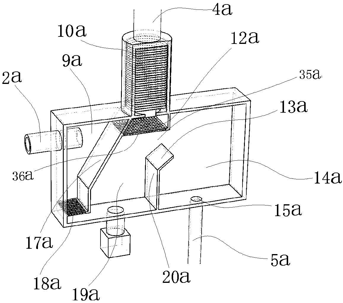
[0029] as attached Figures 1 to 4As shown, an oil-gas separation device of a hot oil circulation system is characterized in that: it includes an oil-gas separation device 3, and the oil-gas separation device 3 includes an oil-gas separation box 22a; the oil-gas separation box 22a includes a first partition plate 20a , the first partition plate 20a divides the inner cavity of the oil-gas separation box 22a into a left chamber and a right chamber 14a, the lower end of the first partition plate 20a is connected to the bottom of the oil-gas separation box 22a, and the upper end of the first partition plate 20a There is a liquid overflow channel 35a between the top of the oil-gas separation box 22a; when the liquid in the left chamber reaches the upper end of the first partition plate 20a, it will overflow into the right chamber 14a; it also includes the second partition p...


PUM


Abstract

The invention discloses an oil-gas separation device of a hot oil circulation system. The oil-gas separation device comprises an oil-gas separation device body. The oil-gas separation device body comprises an oil-gas separation box. A first division plate is included in the oil-gas separation box and divides an inner cavity of the oil-gas separation box into a left cavity and a right cavity. The lower end of the first division plate is connected with the box bottom of the oil-gas separation box. A liquid overflow channel is arranged between the upper end of the first division plate and the boxtop of the oil-gas separation box. When liquid in the left cavity reaches the upper end of the first division plate, the liquid can overflow into the right cavity. A second division plate is furtherincluded and obliquely divides the left cavity into an oil inlet cavity and a transition cavity. The oil-gas separation device is simple in structure, an overflow type first division plate semi-division structure is adopted, the effect of bubble overflow is achieved, and the function of stopping precipitate is also achieved.

Description

technical field [0001] The invention belongs to the field of boilers, and in particular relates to an oil-gas separation device of a thermal oil circulation system and a method thereof. Background technique [0002] The gas-fired hot oil boiler uses heat-conducting oil as the medium, and uses the hot oil circulating oil pump to force the medium to circulate in liquid phase, and then transfers the heat energy to the heat-consuming equipment and then returns to the heating furnace for reheating. , Air bubbles are easy to form in the pipeline. If the bubbles are not overflowed in time, the pressure in the pipeline will increase and the equipment will be damaged. A large amount of heat is not utilized in the flue gas discharged from the boiler. Contents of the invention [0003] Purpose of the invention: In order to overcome the deficiencies in the prior art, the present invention provides an oil-gas separation device and method for a thermal oil circulation system. [0004]...

Claims


Application Information

Patent Timeline
Patent Type & Authority Applications(China)
IPC IPC(8): F24H9/00B01D50/00F24H7/00F24H9/18F23L15/02
CPCF23L15/02F24H7/005F24H9/0005F24H9/18B01D50/20Y02E20/34
Inventor 崔小勤
Owner 崔小勤
Features
  • R&D
  • Intellectual Property
  • Life Sciences
  • Materials
  • Tech Scout
  • Unparalleled Data Quality
  • Higher Quality Content
  • 60% Fewer Hallucinations
Learn More