Strain sensor
A technology of strain sensor and deformation variable, applied in the field of strain sensor, can solve problems such as narrow application range, and achieve the effect of large detection range and fast response speed
- Summary
- Abstract
- Description
- Claims
- Application Information
AI Technical Summary
Problems solved by technology
Method used
Image


Examples
Embodiment Construction
[0015] The strain sensor provided by the present invention will be further described below with reference to the drawings and specific embodiments.
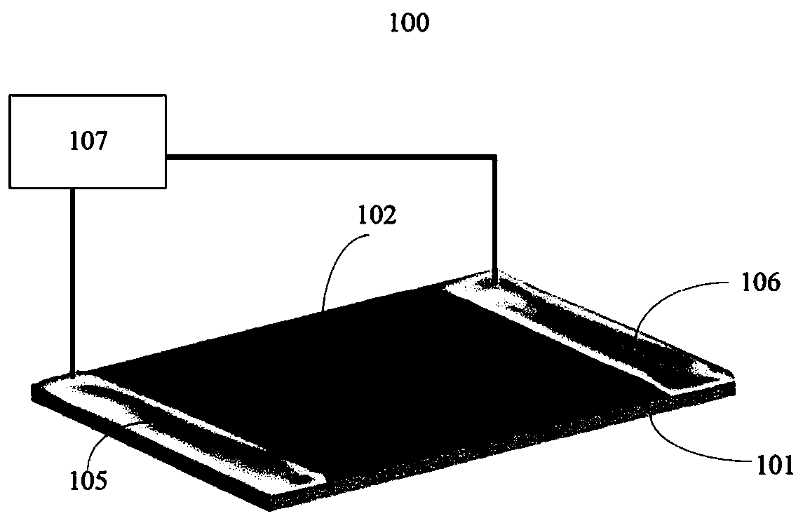
[0016] see figure 1 , the first embodiment of the present invention provides a strain sensor 100 , the strain sensor 100 includes: a substrate 101 , a carbon nanotube film 102 , a first electrode 105 , a second electrode 106 and a detector 107 . The matrix 101 and the carbon nanotube film 102 form a composite structure. The carbon nanotube film 102 is disposed on the surface of the substrate 101 and fixed. The first electrode 105 and the second electrode 106 are respectively arranged at two ends of the carbon nanotube film 102 and electrically connected with the carbon nanotube film 102 . The detector 107 is used to detect the resistance value of the carbon nanotube film 102 and is electrically connected to the first electrode 105 and the second electrode 106 .
[0017] The matrix 101 mainly plays a supporting role for providi...
PUM
 Abstract
Description
Claims
Application Information
 - Generate Ideas
- Intellectual Property
- Life Sciences
- Materials
- Tech Scout
- Unparalleled Data Quality
- Higher Quality Content
- 60% Fewer Hallucinations
Browse by: Latest US Patents, China's latest patents, Technical Efficacy Thesaurus, Application Domain, Technology Topic, Popular Technical Reports.
© 2025 PatSnap. All rights reserved.Legal|Privacy policy|Modern Slavery Act Transparency Statement|Sitemap|About US| Contact US: help@patsnap.com