
90-degree over-mode waveguide TE01-TM11 mode converter

A mode conversion and over-mode waveguide technology, applied to waveguide devices, electrical components, circuits, etc., can solve problems such as inconvenient docking and limited working bandwidth, and achieve the effects of simple structure, improved efficiency, and reduced use

Active Publication Date: 2018-02-23
UNIV OF ELECTRONIC SCI & TECH OF CHINA
View PDF1 Cites 0 Cited by
  • Summary
  • Abstract
  • Description
  • Claims
  • Application Information

AI Technical Summary

Problems solved by technology

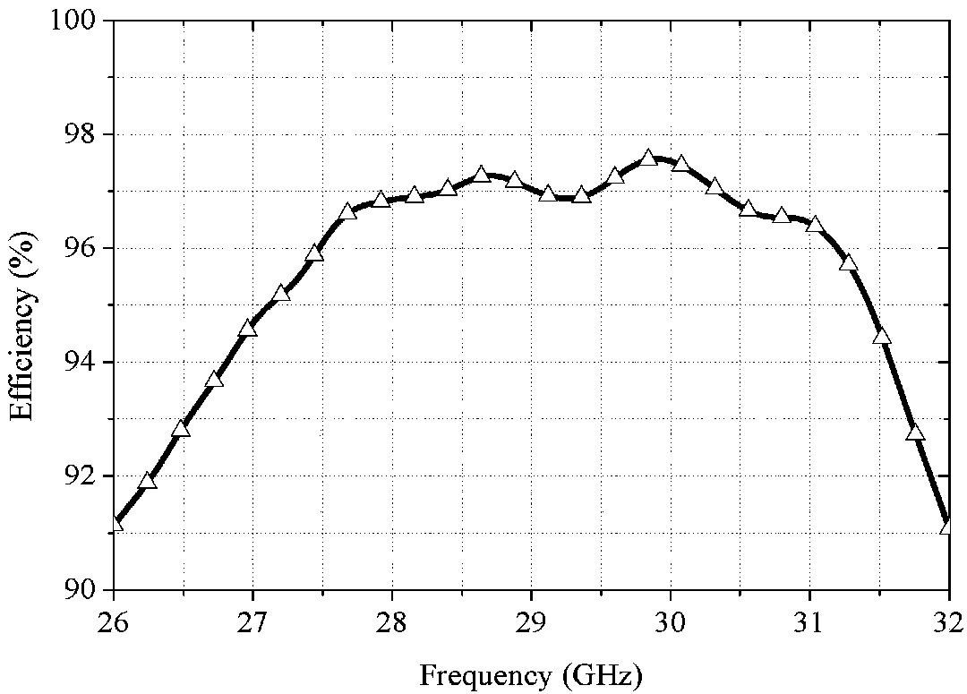
[0007] For the existing TE in the background technology 01 -HE 11 In the mode conversion technology, there are problems of limited working bandwidth and irregular output angles that make docking inconvenient. The present invention provides a broadband, high-efficiency 90 over-mode waveguide TE 01 -TM 11 mode converter, the te 01 modulo efficiently converts to TM 11 Mode at the same time, realize 90-degree turn, easy to realize compact high-power millimeter-wave system

Method used


Image

  • 90-degree over-mode waveguide TE01-TM11 mode converter
  • 90-degree over-mode waveguide TE01-TM11 mode converter
  • 90-degree over-mode waveguide TE01-TM11 mode converter

Examples


no. 1 example

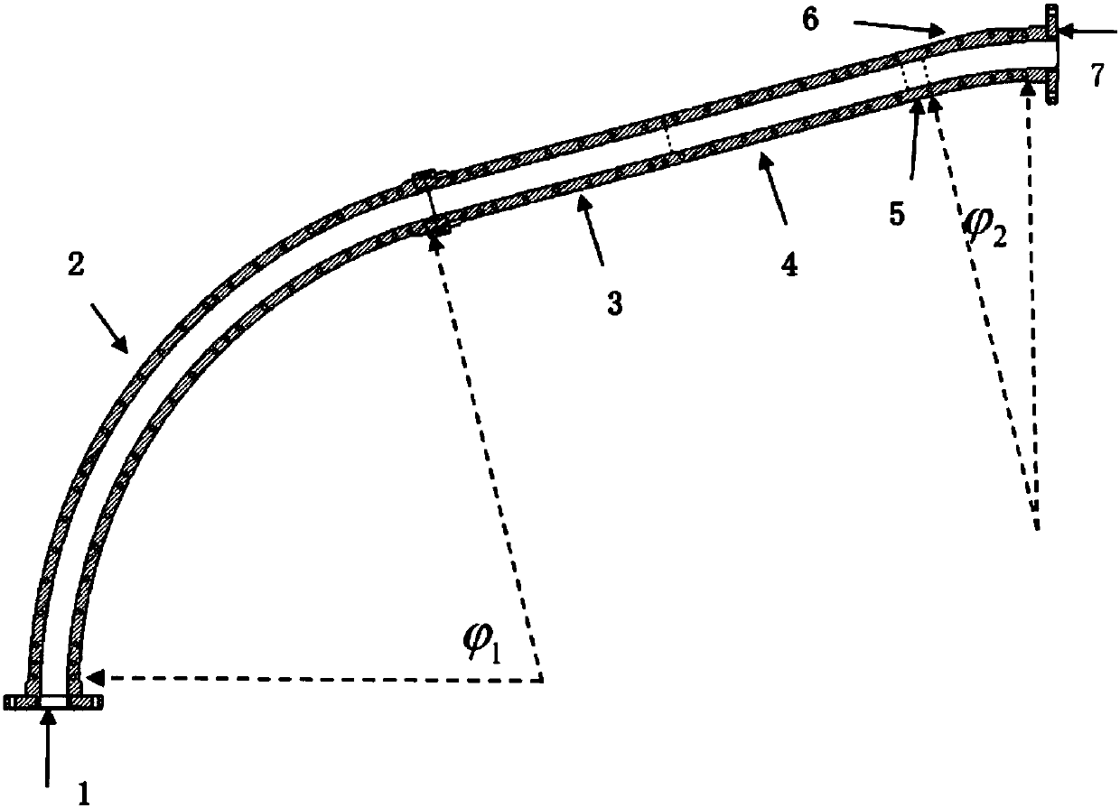
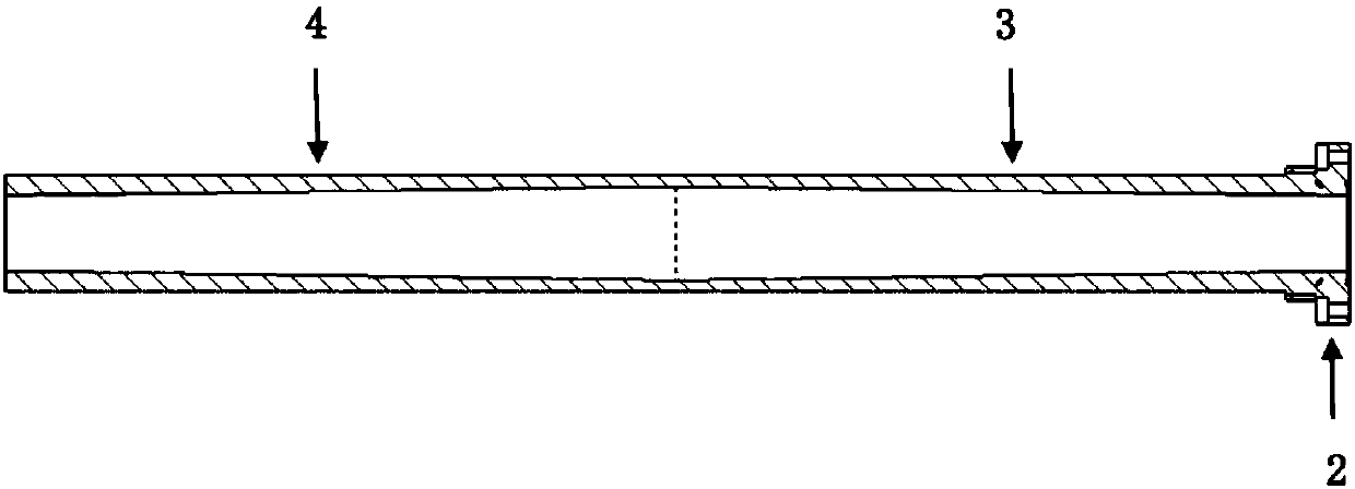
[0049] In the case where the length of the axial direction of the input end is short, that is, in the , The passing angle is TE 01 Convert all to TM 11 Pattern, then go through After reaching the phase reversal section, at this time TM 11 Part of the model has been converted to TE 01 , And TM 11 Mode phase lag TE 01 Mode 90 degrees. After the phase reversal section TM 11 Mode leading TE 01 Mode 90 degrees. In the uniform phase shift section, the modes do not couple. After the uniform phase shift section, the waveguide enters the second mode conversion section due to the bending of the waveguide. 01 Mode to TM 11 Mode conversion coupling. after The second mode of the angle reaches the output port after the second mode change section, at this time TE 01 Fully converted to TM 11 mode.

[0050] In this embodiment, the axial length of the input end is shorter, that is The input waveguide radius is 12.4mm, the turning radius R of the first mode conversion section and the second mo...

no. 2 example

[0054] In the case where the length of the axial direction of the input end is long, that is, in the In the case of the angle After the first mode change section, TE 01 Partially converted to TM 11 Mode, at this time TM 11 Mode phase lead TE 01 Mode 90 degrees. After the phase reversal section, TM 11 Mode phase lag TE 01 Mode 90 degrees. After the uniform phase shift section, the waveguide enters the second mode conversion section due to the bending of the waveguide, making the TM 11 Mode to TE 01 Mode conversion coupling. The passing angle in the second mode conversion section is After the bending section, the TM is excited 11 Mode fully converted to TE 01 mode. From To the output port, TE 01 To TM 11 Conversion, fully converted to TM at the output port 11 mode.

[0055] The structural parameters in this embodiment are as follows: the radius of the input circular waveguide is 12.6 mm. The turning radius R of the two-mode conversion section is 375mm, and the angle of the fi...


PUM


Abstract

The invention discloses a 90-degree over-mode waveguide TE01-TM11 mode converter, which belongs to the technical field of microwave millimeter waves. The waveguide mode converter comprises a first mode transforming section, a phase reversing section, a uniform phase shifting section and a second mode transforming section, wherein the first mode transforming section, the phase reversing section, the uniform phase shifting section and the second mode transforming section are sequentially connected. The joints of internal cavities of the structures of the sections are in smooth transition. According to the invention, the input port and the output port of the waveguide mode converter are 90 degrees, which is convenient for butt joint of the system; when 90-degree turning is realized, the operating mode is transformed from TE01 to TM11; the converter has the functions of a waveguide mode converter and an elbow, which helps to reduce uses transmission devices; and the efficiency of the entire system is improved; and the position where the phase reversing section is located is selected according to the actual situation, so as to adjust the axial length of the output end and the input endof the device according to the actual situation.

Description

Technical field [0001] The invention belongs to the technical field of microwave and millimeter waves, and specifically relates to a high-power microwave over-mode waveguide elbow mode converter. Background technique [0002] With the rapid development of technologies such as electronic countermeasures, microwave weapons, and radar communications, the millimeter wave frequency band has received more and more attention, and has gradually become a hot spot for competition in fields such as military defense and civilian industry. In the 1990s, high-power millimeter-wave sources made considerable progress, the most representative of which is the development of cyclotron devices. At present, a series of millimeter-wave high-power sources have been developed internationally, such as gyro-oscillating tube, gyro traveling wave amplifier tube, gyro-klysonic amplifier tube, and gyro-backwave tube. In the gyro device family, the gyro traveling wave tube is widely used in millimeter-wave hi...

Claims


Application Information

Patent Timeline
IPC IPC(8): H01P1/163
CPCH01P1/163
Inventor 吴泽威廖校毅王建勋蒲友雷蒋伟罗勇
Owner UNIV OF ELECTRONIC SCI & TECH OF CHINA
Learn More