Broadband high-power millimeter-wave over-mode waveguide TE01 directional coupler

A technology of directional coupler and over-mode waveguide, which is applied in the direction of waveguide devices, electrical components, connecting devices, etc., can solve the problems of low directivity and low power capacity, and achieve high directivity, large power capacity and coupling degree smooth effect

Active Publication Date: 2018-02-23
UNIV OF ELECTRONICS SCI & TECH OF CHINA
View PDF4 Cites 7 Cited by
  • Summary
  • Abstract
  • Description
  • Claims
  • Application Information

AI Technical Summary

Problems solved by technology

[0007] In view of the shortcomings of the existing high-power millimeter-wave directional coupler such as low power capacity and low directivity, and the requirements of high-power millimeter-wave transmission systems for high mode selection characteristics and anti-standing waves, the present invention proposes an overmode-based TE of quadrupole main waveguide structure 01 Directional Coupler Technical Solution

Method used


Image

  • Broadband high-power millimeter-wave over-mode waveguide TE01 directional coupler
  • Broadband high-power millimeter-wave over-mode waveguide TE01 directional coupler
  • Broadband high-power millimeter-wave over-mode waveguide TE01 directional coupler

Examples


Embodiment Construction

[0036] Combining the above theoretical basis and design points, the Ka-band TE 01 The design of a mode broadband directional coupler is illustrated as an example.

[0037] In this embodiment, considering the power level on the existing high-power transmission link and the conditions of the detection equipment, the indicators of the directional coupler are required as follows: working frequency band: 26GHz-40GHz; coupling degree greater than 35dB; directivity greater than 35dB; the in-band coupling fluctuation is less than ±2dB.

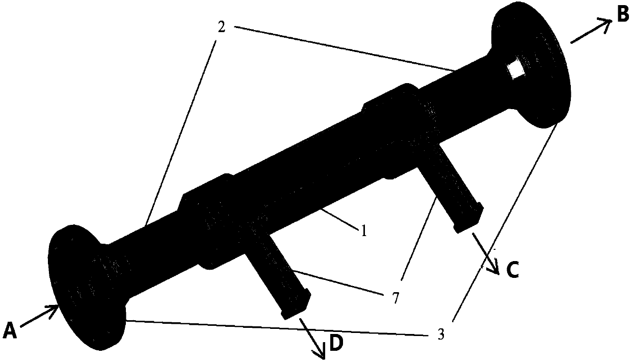
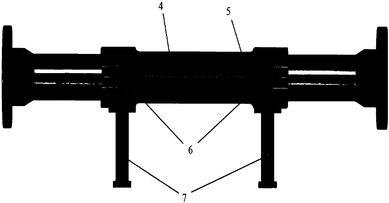
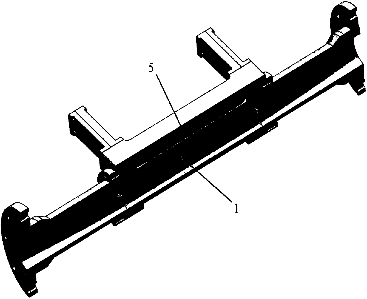
[0038] as attached figure 1 As shown, the overmode waveguide TE of this embodiment 01 The directional coupler includes: an overmoded four-pole main waveguide, an input transition section and an output transition section symmetrically arranged at both ends thereof, and a secondary waveguide that communicates with the convex part of the overmode four-pole main waveguide through a row of coupling holes. The input transition section and the output tran...


PUM


Abstract

The invention, which belongs to the technical field of high-power millimeter-wave devices, discloses a broadband high-power millimeter-wave over-mode waveguide TE01 directional coupler comprising an over-mode quadrupole main waveguide, an input transition section, an output transaction section, and an auxiliary waveguide communicated with a protrusion part of the over-mode quadrupole main waveguide by one row of circular coupling holes. The input transition section and the output transaction section are arranged at the two ends of the main waveguide symmetrically. According to the invention, on the basis of the over-mode quadrupole waveguide structure, the power capacity is large and output characteristics of stable coupling and high directivity are realized in a broadband range; the modespacing is large in the quadrupole waveguide, so that the directional coupler has high mode selectivity and thus influences by other parasitic modes are eliminated; and on the basis of the quadrupolewaveguide structure, the high-directivity index is realized and the directional coupler has the anti-standing wave characteristic.

Description

technical field [0001] The invention belongs to the technical field of high-power millimeter-wave devices, and in particular relates to a directional coupler for power detection on a high-power millimeter-wave transmission link. Background technique [0002] Directional coupler is a kind of microwave and millimeter-wave device widely used in microwave system. Its main function is to perform power detection and spectrum measurement on high-power signals. Usually, a directional coupler is composed of a main waveguide and a secondary waveguide, where the main waveguide is used for the transmission of high-power signals, and the secondary waveguide is used to couple out part of the power for detection and then calculate the energy transmitted in the main waveguide. Waveguide structures such as coaxial lines, striplines, microstrip lines, rectangular waveguides, and circular waveguides can all implement directional couplers. [0003] The cyclotron traveling wave tube is currentl...

Claims


Application Information

Patent Timeline
Patent Type & Authority Applications(China)
IPC IPC(8): H01P5/18
CPCH01P5/18
Inventor 吴泽威宋俊逸王建勋蒲友雷蒋伟陈楷文罗勇
Owner UNIV OF ELECTRONICS SCI & TECH OF CHINA
Why Eureka
Try Eureka