Automatic cable laying equipment and method

A technology for laying equipment and cables, which is applied in the field of automatic cable laying equipment, which can solve the problems of restricting the shipbuilding industry, limited construction space, harsh working environment, etc., and achieve the effect of avoiding manual laying, easy operation, and satisfying volume

Inactive Publication Date: 2018-02-23
FUJIAN MAWEI SHIPBUILDING
View PDF6 Cites 3 Cited by
  • Summary
  • Abstract
  • Description
  • Claims
  • Application Information

AI Technical Summary

Problems solved by technology

However, the existing cable laying for marine electrical installations is all manual laying, with a few or a dozen or even dozens of workers standing in a row, respectively distributed at various points in the laying channel, and laying cables in relay mode. However, many factors during the laying operation process, such as long construction period, harsh working environment, limited construction space, manual laying, easy to cause cable entanglement and mechanical damage to the cable, have brought great inconvenience to the worker's operation process, and also restricted it to a certain extent. development of the shipbuilding industry

Method used


Image

  • Automatic cable laying equipment and method
  • Automatic cable laying equipment and method
  • Automatic cable laying equipment and method

Examples


Embodiment 1

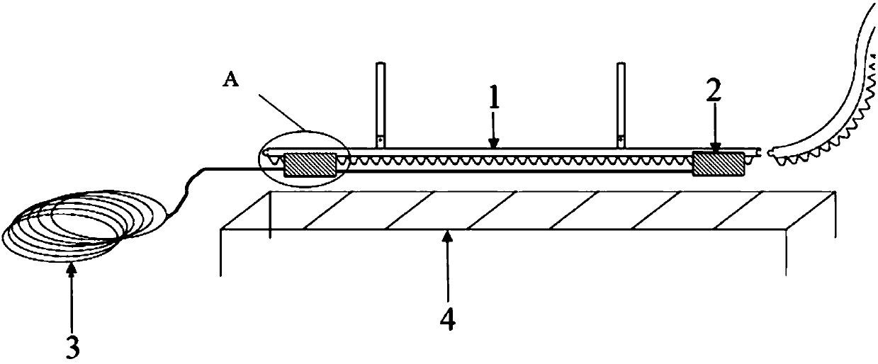
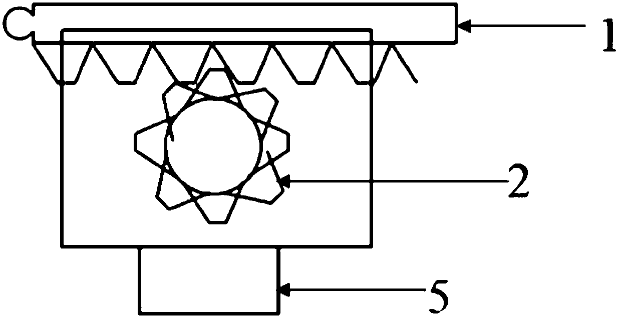
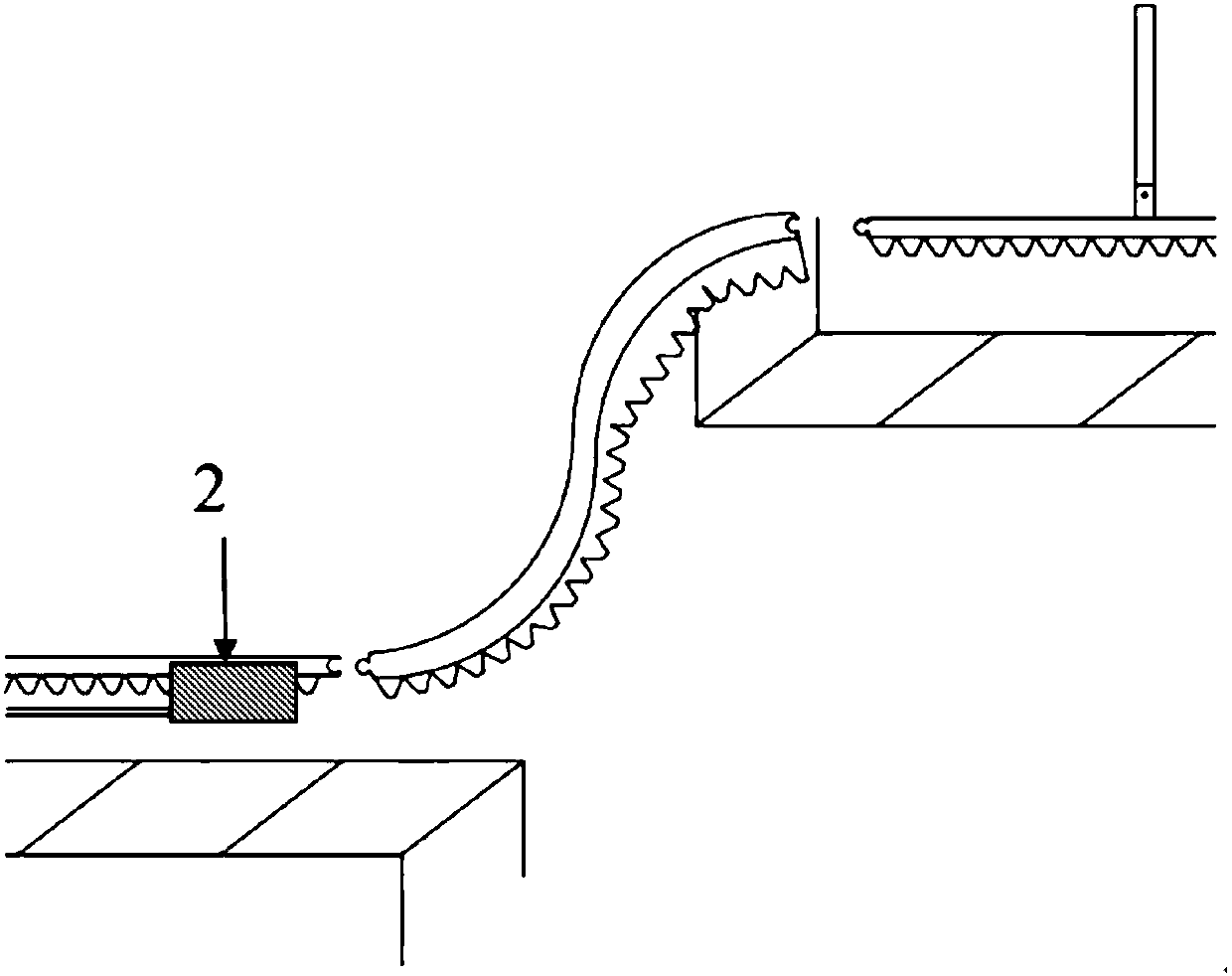
[0040] Please refer to Figures 1 to 3 As shown, the first embodiment of the present invention is: an automatic cable laying equipment, including at least two traction motors 2, cable guide rails 1, cable clamps 5 and a control system, the output shaft of the traction motor 2 is provided with a traction gear , the lower surface of the cable guide rail 1 is provided with a rack; the rack is meshed with the traction gear, the cable clamp 5 is installed below the traction motor 2, and the cable clamp 5 is connected to the control system connected; the cable guide rail 1 is composed of a plurality of guide rail segments, one end of the guide rail segment is provided with a groove, and the other end is provided with a protrusion matching the groove. The end of the cable guide 1 is provided with a limiting device. The guide rail section includes a straight guide rail section and an elbow guide rail section. The elbow-shaped guide rail section is S-shaped. The laying equipment als...

Embodiment 2

[0041] Embodiment 2 of the present invention is: an automatic cable laying equipment, including at least two traction motors 2, cable guide rails 1, cable clamps 5 and a control system, the output shaft of the traction motor 2 is provided with a traction gear, the The lower surface of the cable guide rail 1 is provided with a rack; the rack is meshed with the traction gear, the cable clamp 5 is installed below the traction motor 2, and the cable clamp 5 is connected to the control system; The cable guide rail 1 is composed of a plurality of guide rail sections, one end of the guide rail section is provided with a groove, and the other end is provided with a protrusion matching the groove. The end of the cable guide 1 is provided with a limiting device. The guide rail section includes a straight guide rail section and an elbow guide rail section. The elbow-shaped guide rail section is S-shaped. The laying equipment also includes a motor mounting plate, which is used for mount...

Embodiment 3

[0042] Embodiment 3 of the present invention is: an automatic cable laying method, comprising the following steps:

[0043] S1. Install the cable guide rail 1 above the peripheral cable bracket 4;

[0044] S2. Control the cable clamp 5 to automatically clamp the cable 3 through the control system, and move forward under the drive of the traction motor 2;

[0045] S3. After the traction motor moves to a designated position, control the cable clamp 5 to release, and the cable 3 falls naturally on the bracket 4 .

[0046] In summary, the present invention provides automatic cable laying equipment and a laying method, which have a wide application range and are easy to operate.


PUM


Abstract

The invention provides automatic cable laying equipment and method. The automatic cable laying equipment comprises at least two traction motors, a cable guide rail, a cable clamp and a control system,wherein a traction gear is arranged on an output shaft of the traction motor, a rack is arranged on the lower surface of the cable guide rail, the rack is meshed with the traction gear, the cable clamp is arranged below the traction motor, and the cable clamp is connected with the control system; the cable guide rail is composed of a plurality of guide rail sections, a groove is formed in one endof each guide rail section, and the other end of each guide rail section is provided with a protrusion matched with the corresponding groove. The laying method comprises the step of installing the cable guide rail, the step of driving a cable to move through the traction motor, and the step of loosening the cable clamp to make a bracket fall. Compared with the prior art, the automatic laying equipment is of a simple structure, and the laying method has the advantages of being simple and convenient to operate and the like.

Description

technical field [0001] The invention relates to the field of marine cable laying, in particular to an automatic cable laying equipment and a laying method. Background technique [0002] With the development and utilization of marine resources, the shipbuilding industry is in a period of rapid development. Ship cable laying is one of the lifeblood of ship construction, and the cable laying project usually occupies more than half of the electrical part of the entire ship construction. However, the existing cable laying for marine electrical installations is all manual laying. A few or a dozen or even dozens of workers stand in a row and are distributed at various points in the laying channel. The relay method is used to lay cables. However, many factors during the laying operation, such as long construction period, harsh working environment, limited construction space, manual laying, easy to cause cable entanglement and mechanical damage to the cable, have brought great incon...

Claims


Application Information

Patent Timeline
Patent Type & Authority Applications(China)
IPC IPC(8): H02G1/08
CPCH02G1/088
Inventor 胡启越
Owner FUJIAN MAWEI SHIPBUILDING
Why Eureka
Try Eureka