Overvoltage optimal inhibiting method based on high-voltage direct-current power transmission reactive power control

A high-voltage direct current transmission and direct current transmission system technology, which is applied in emergency protection circuit devices for limiting overcurrent/overvoltage, reactive power compensation, and AC network circuits, etc., to suppress the generation of overvoltage and increase reactive power. Effect

Active Publication Date: 2018-02-23
STATE GRID SICHUAN ELECTRIC POWER CORP ELECTRIC POWER RES INST +1
View PDF7 Cites 7 Cited by
  • Summary
  • Abstract
  • Description
  • Claims
  • Application Information

AI Technical Summary

Problems solved by technology

[0005] The technical problem to be solved by the present invention is the overvoltage of the AC power grid during the single-circuit DC fault of the multi-DC centralized external transmission network. During the fault period, the shutdown angle γ and the DC current

Method used


Image

  • Overvoltage optimal inhibiting method based on high-voltage direct-current power transmission reactive power control
  • Overvoltage optimal inhibiting method based on high-voltage direct-current power transmission reactive power control
  • Overvoltage optimal inhibiting method based on high-voltage direct-current power transmission reactive power control

Examples


Embodiment 1

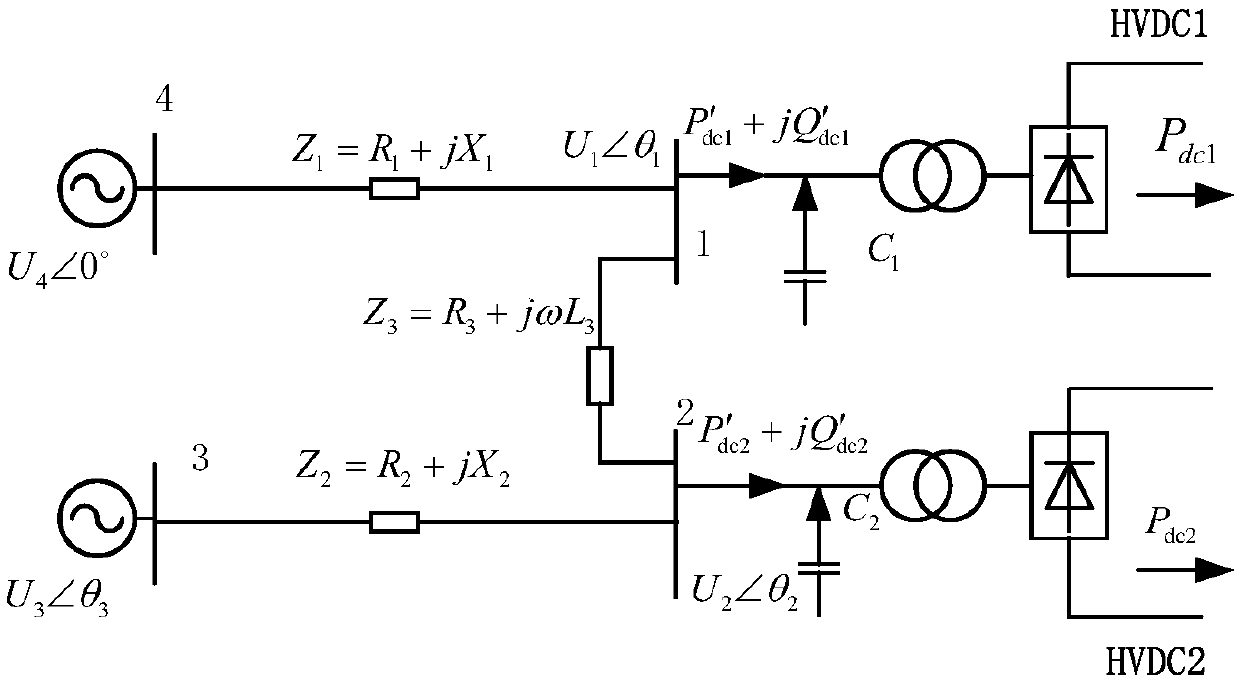
[0089] This embodiment takes figure 1 Take the power grid shown as an example, set 0-time 2# DC to perform phase-shift operation due to faults, when the short circuit of the AC system is relatively low, the system overvoltage risk is high, and the overvoltage risk is most obvious in the 2# DC AC converter station bus. The following will consider the additional control of 1# DC to limit the overvoltage of 2# bus by increasing the γ angle.

[0090] In order to highlight the features, make the following settings:

[0091] 1. Due to the relatively high short-circuit ratio of the AC system at the receiving end, the voltage of the AC busbar on the 1# DC inverter side is constant during the setting control period;

[0092] 2. Neglect the effect of commutation overlap angle;

[0093] 3. For multiple DC feed-in grids, the transmission line distance between 1# DC and 2# DC converter stations generally does not exceed 30km, and it is approximately considered that the AC bus voltage of...

Embodiment 2

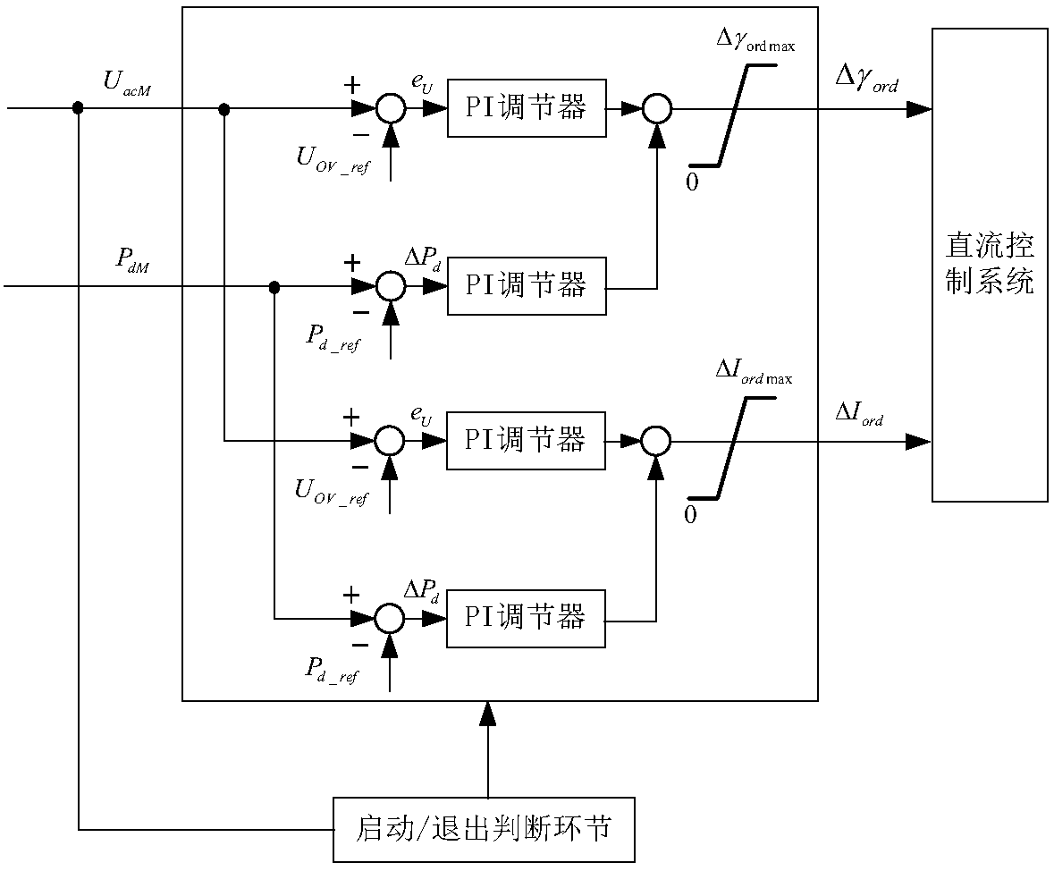
[0151] Present embodiment obtains such as on the basis of embodiment 1 image 3 As shown in the block diagram of the overvoltage suppression link, the overvoltage suppression control proposed in this paper takes the AC side bus voltage and DC output power as the control targets, and uses the optimal PI control method to measure the rectifier side AC bus voltage and DC power in real time. Obtain the turn-off angle additional command △γord and the DC current additional control value △Iord, and send them to the DC control system. The choice of optimal PI parameters is calculated by .

[0152] image 3 The main parameter definitions and reference values ​​are as follows:

[0153] u OV_ref : AC bus voltage control setting value. The value of this physical quantity should ensure that the overvoltage protection will not operate during the duration of the fault in the converter station.

[0154] u OV_ref ≤k rel u OV

[0155] In the formula, krel is the reliability coefficient...


PUM


Abstract

The invention discloses an overvoltage optimal inhibiting method based on high-voltage direct-current power transmission reactive power control. The method comprises the steps that 1, it is set that adirect-current power transmission inversion side is controlled by a prediction-type fixed extinction angle, a rectification side is controlled by constant current, and according to a direct-current power transmission system control principle, a linearization control equation is obtained; 2, a P-Q decomposition method is utilized to obtain a reactive power flow correction equation of a direct-current near zone according to the running mode of a multi-direct-current feed-out near-zone power grid, and thus a direct-current near-zone power flow linearization equation is obtained; 3, a system state equation is obtained; 4, a PI state adjuster is obtained. By means of the overvoltage optimal inhibiting method based on the high-voltage direct-current power transmission reactive power control, amethod of increasing near-zone direct-current inversion-side turn-off angle gamma to conduct overvoltage inhibition is put forward. In a sharp rising phase of alternating current network voltage, by controlling the near-zone inversion-side turn-off angle gamma and a direct-current instruction value, on the basis of maintaining the power constancy of the near-zone sound direct-current power transmission system, the reactive power consumed by a current converter is improved within a short time, and the occurrence of overvoltage of a feeding end weak alternating current network is inhibited.

Description

technical field [0001] The invention relates to the field of high-voltage direct current transmission, in particular to an optimal overvoltage suppression method based on reactive power control of high-voltage direct current transmission. Background technique [0002] Due to its advantages in long-distance large-capacity power transmission and asynchronous grid interconnection, HVDC technology has been rapidly developed and widely used in China, India, South Korea, Brazil and other countries. The current source DC transmission system uses thyristor as the main commutation element, and consumes 50% to 60% of the reactive power of the transmission power during normal operation. Taking the ±800kV / 8000MW UHV DC transmission system as an example, the thyristor converter and the converter transformer consume nearly 6400Mvar of reactive power during full power operation. In order to eliminate the influence of a large amount of reactive power consumption on the reactive power flow ...

Claims


Application Information

Patent Timeline
IPC IPC(8): H02H9/04H02J3/18H02J3/36
CPCH02H9/04H02J3/1807H02J3/36H02J2203/20Y02E40/30Y02E60/60
Inventor 朱清代滕予非张鹏李小鹏张纯代宇涵孙永超罗荣森段翔兮
Owner STATE GRID SICHUAN ELECTRIC POWER CORP ELECTRIC POWER RES INST
Why Eureka
Try Eureka