
Receiving end circuit for wireless charging and vehicle using same

A wireless charging and receiving end technology, applied in battery circuit devices, electric vehicles, vehicle energy storage, etc., can solve the problem of high filter capacitor voltage and achieve the effect of protection from damage

Active Publication Date: 2018-02-23
XJ POWER CO LTD +2
View PDF3 Cites 5 Cited by
  • Summary
  • Abstract
  • Description
  • Claims
  • Application Information

AI Technical Summary

Problems solved by technology

[0006] The purpose of the present invention is to provide a receiving end circuit for wireless charging, which is used to solve the problem that the voltage of the filter capacitor is too high when the load is suddenly removed during the charging process

Method used


Image

  • Receiving end circuit for wireless charging and vehicle using same
  • Receiving end circuit for wireless charging and vehicle using same

Examples


Embodiment Construction

[0024] An embodiment of a receiving end circuit for wireless charging of the present invention:

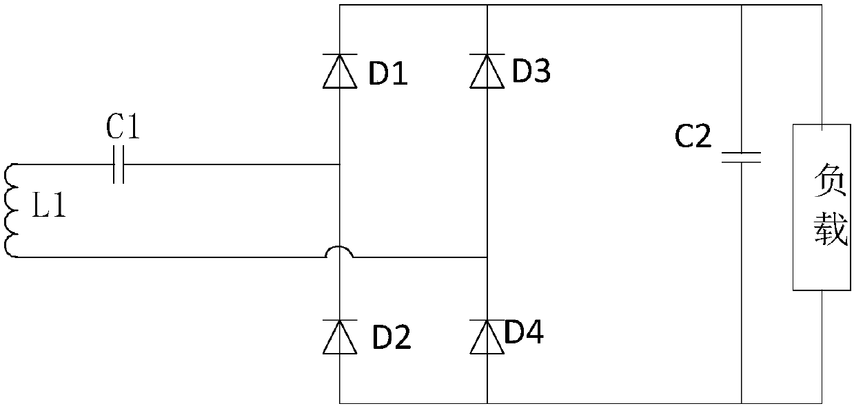
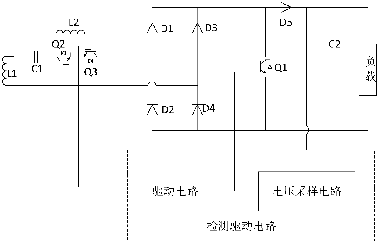
[0025] A receiving end circuit for wireless charging includes a resonant module, a rectifier module, and a filter capacitor. The resonant module includes a resonant inductor and a resonant capacitor and is connected to the AC side of the rectifier module. The filter capacitor is connected to the rectifier module. It is connected to the DC side and used to connect to the load, and also includes a protection branch connected between the resonance module and the AC side of the rectifier module, connected to the DC side of the rectifier module, and used to connect in parallel with the filter capacitor A protection switch tube and a detection drive circuit; the protection branch includes a first branch and a second branch connected in parallel, wherein the first branch is provided with a switch tube, and the second branch is provided with a protective inductor; in normal operation , The p...


PUM


Abstract

The invention discloses a receiving end circuit for wireless charging and a vehicle using the same. The receiving end circuit comprises a resonance module, a rectifier module and a filtering capacitor. The resonance module comprises a resonant inductor and a resonant capacitor, and is connected with the AC side of the rectifier module; and the filtering capacitor is connected with the DC side of the rectifier module. The receiving end circuit also comprises a protection branch connected between the resonance module and the AC side of the rectifier module, a protection switch tube connected atthe DC side of the rectifier module and connected in parallel with the filtering capacitor, and a detection driving circuit. The protection branch comprises a first branch and a second branch. The first branch is provided with a switching switch tube; and the second branch is provided with a protection inductor. During normal working, the protection switch tube is cut off, the first branch is connected, and the second branch is bypassed; and when a protection effect is achieved, the protection switch tube is connected, the first branch is disconnected, and the second branch is connected in series in the circuit. The problem of capacitor overvoltage due to sudden unloading of the load in the charging process is solved.

Description

Technical field [0001] The invention relates to the field of electric vehicle charging, in particular to a receiving end circuit for wireless charging and a vehicle using the circuit. Background technique [0002] Wireless charging of electric vehicles is an emerging technology in recent years, which can charge electric vehicles without a charging cable. A device based on wireless power transmission technology refers to a device that does not require metal wires to be connected between the transmitting end and the receiving end of the electrical energy for electrical energy transmission. It separates the power supply from the corresponding load, which is not only convenient to use, but also eliminates the need for electrical energy transmission. In the process, the electric sparks that may be generated when the switch contacts and closes, the application of wireless power transmission technology in the occasions where pyrotechnics is strictly prohibited becomes safer and more rel...

Claims


Application Information

Patent Timeline
IPC IPC(8): H02J50/12H02J7/02H02H7/16
CPCH02H7/16H02J5/005H02J7/025Y02T10/70Y02T10/7072Y02T10/72Y02T90/14
Inventor 陈天锦黄栋杰范金焰邓思维张滨曹亚韩海伦
Owner XJ POWER CO LTD
Learn More