Radio link management method and device

A wireless link and management method technology, applied in the field of wireless link management methods and devices, capable of solving problems such as poor mobility of terminals

Inactive Publication Date: 2018-02-23
ZTE CORP
View PDF6 Cites 6 Cited by
  • Summary
  • Abstract
  • Description
  • Claims
  • Application Information

AI Technical Summary

Problems solved by technology

[0017] Embodiments of the present invention provide a wireless link management method and device, to at least solve the problem of poor terminal mobility caused b

Method used


Image

  • Radio link management method and device
  • Radio link management method and device
  • Radio link management method and device

Examples


Embodiment 1

[0072] In this embodiment, a radio link management method is provided, Figure 6 is a flowchart of a radio link management method according to an embodiment of the present invention, such as Figure 6 As shown, the process includes the following steps:

[0073] Step S602, receiving radio resource management RRM measurement parameters issued by the base station through radio resource control RRC signaling;

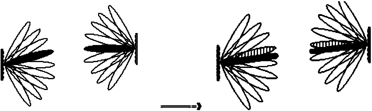
[0074] Step S604, according to the RRM measurement parameter, perform RRM measurement on multiple or all beams under the jurisdiction of the target beamforming BF splitting base station transmission and reception point TRP, and obtain the RRM measurement result;

[0075] Step S606, jointly evaluate the RRM measurement result based on multiple or all beams, and switch from the source BF offload base station TRP to the target BF offload base station TRP or additionally add the target BF offload base station TRP according to the evaluation result.

[0076] Optionally, in thi...

Embodiment 2

[0114] Such as Figure 9 As shown, the main reason is that the UE was originally in the dual-connection data transmission state between the MeNB and a certain source Beam of TRP 1, but was later switched to the dual-connection data transmission state between the MeNB and a certain Beam of TRP 2 due to the movement of the UE.

[0115] next to Figure 9 Describe in detail.

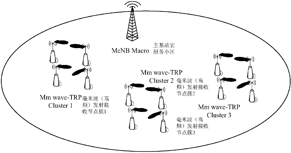
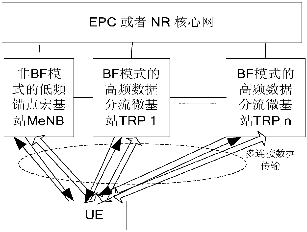
[0116] An operator deploys and utilizes high and low frequency tight coupling for dual-connection DC operation. There is Pcell service macro cell coverage on a certain licensed carrier where the low-frequency main control anchor base station MeNB is located, and the remote end connects to the SeNB high-frequency through the X2 interface. Distribute the two nodes of the base station TRP1 and TRP2. There is one TRP1 and one TRP2 on a high-frequency licensed carrier where the SeNB node is located, and they respectively govern the deployment of four service Beams for capacity enhancement in hotspot areas.

[0...

Embodiment 3

[0125] Such as Figure 10 As shown, the UE was originally in the dual-connection data transmission state of NR(m) BS and a source Beam of TRP 1, but was switched to the dual-connection data transmission state of NR(m) BS and a certain Beam of TRP 2 due to UE movement.

[0126] next to Figure 10 Describe in detail.

[0127] An operator deploys and utilizes high and low frequency tight coupling for dual-connection DC operation. There is Pcell service macro cell coverage on a licensed carrier where the low-frequency main control anchor base station NR(m)BS is located. At the remote end, through the Xnew interface, Connect the two nodes of NR(s)BS high-frequency distribution base station TRP1 and TRP2. There is one TRP1 and one TRP2 on a high-frequency licensed carrier where the NR(s)BS node is located, and there are four service beams deployed respectively. Enhanced capacity in hotspot areas.

[0128]Initially, the UE is already under the joint coverage of Pcell and TRP1, so ...


PUM


Abstract

The invention provides a radio link management method and device. The method comprises the steps of receiving a radio resource management RRM measurement parameter issued by a base station through radio resource control RRC signaling; carrying out RRM measurement on a plurality of or all beams managed by a transmit receive point TRP of a target beamforming BF distribution base station according tothe RRM measurement parameter, thereby obtaining an RRM measurement result; and jointly evaluating the RRM measurement result based on the plurality of or all beams, and switching from the TRP of a source BF distribution base station to the TRP of the target BF distribution base station or additionally adding the TRP of the target BF distribution base station according to an evaluation result. Through application of the method and the device, the problem that in related technologies, the terminal mobility performance is relatively low due to the fact that radio resource control measurement evaluation is carried out and mobile switching between beamforming base stations is carried out by taking a single beam as granularity is solved, thereby achieving the effect of improving the terminal mobility performance.

Description

technical field [0001] The present invention relates to the communication field, in particular to a wireless link management method and device. Background technique [0002] In the future (3rd Generation Partnership Project fifth Generation, referred to as 3GPP 5G) newly designed new radio access (New RAT / Radio, referred to as NR) system, the utilization and operation of high-frequency wireless carrier resources will play an increasingly important role. It plays an important role. Through carrier aggregation and tightly coupled multi-connection, wider high-frequency carrier resources can be fully aggregated and utilized to improve NR system capacity and throughput performance. Such as figure 1 As shown, under the wide coverage of low-frequency macro base station cells, operators can enhance the capacity of some hotspot Hotspot areas through high-frequency (mmWave) small base station small cells. Different from traditional Omni-Directional or Sector cell coverage, in order ...

Claims


Application Information

Patent Timeline
IPC IPC(8): H04W24/08H04W24/10H04W36/18H04W36/30
CPCH04W24/08H04W24/10H04W36/30
Inventor 杨立
Owner ZTE CORP
Why Eureka
Try Eureka