Synchronous punching equipment at both ends of a few-shaped steel beam

A type of steel and equipment technology, applied in the field of synchronous punching equipment at both ends of several-shaped steel beams, can solve the problems of complex production, high labor intensity, and low production efficiency, achieve constant speed and stability at both ends, reduce labor intensity, The effect of improving productivity

Active Publication Date: 2019-07-12
芜湖恒驰钢构有限公司
View PDF7 Cites 0 Cited by
  • Summary
  • Abstract
  • Description
  • Claims
  • Application Information

AI Technical Summary

Problems solved by technology

And during existing punching processing, at first adopt four mounting holes (N-1) of an end of this several-shaped steel beam (N) to process on punching equipment, and because this several-shaped steel beam (N) The length is very long (usually ranging from 5-100m), and then the four mounting holes (N-1) at the other end are processed after turning 180° manually. It is bulky, very inconvenient to turn to processing, and there are problems such as complex production, high labor intensity, low production efficiency, and cannot be continuously produced automatically

Method used


Image

  • Synchronous punching equipment at both ends of a few-shaped steel beam
  • Synchronous punching equipment at both ends of a few-shaped steel beam
  • Synchronous punching equipment at both ends of a few-shaped steel beam

Examples


Embodiment Construction

[0038] Below in conjunction with accompanying drawing and embodiment the present invention will be further described:

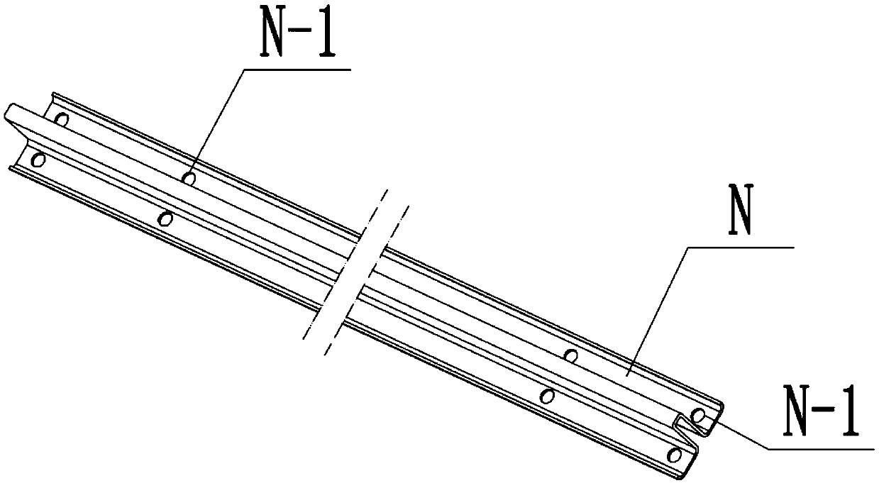
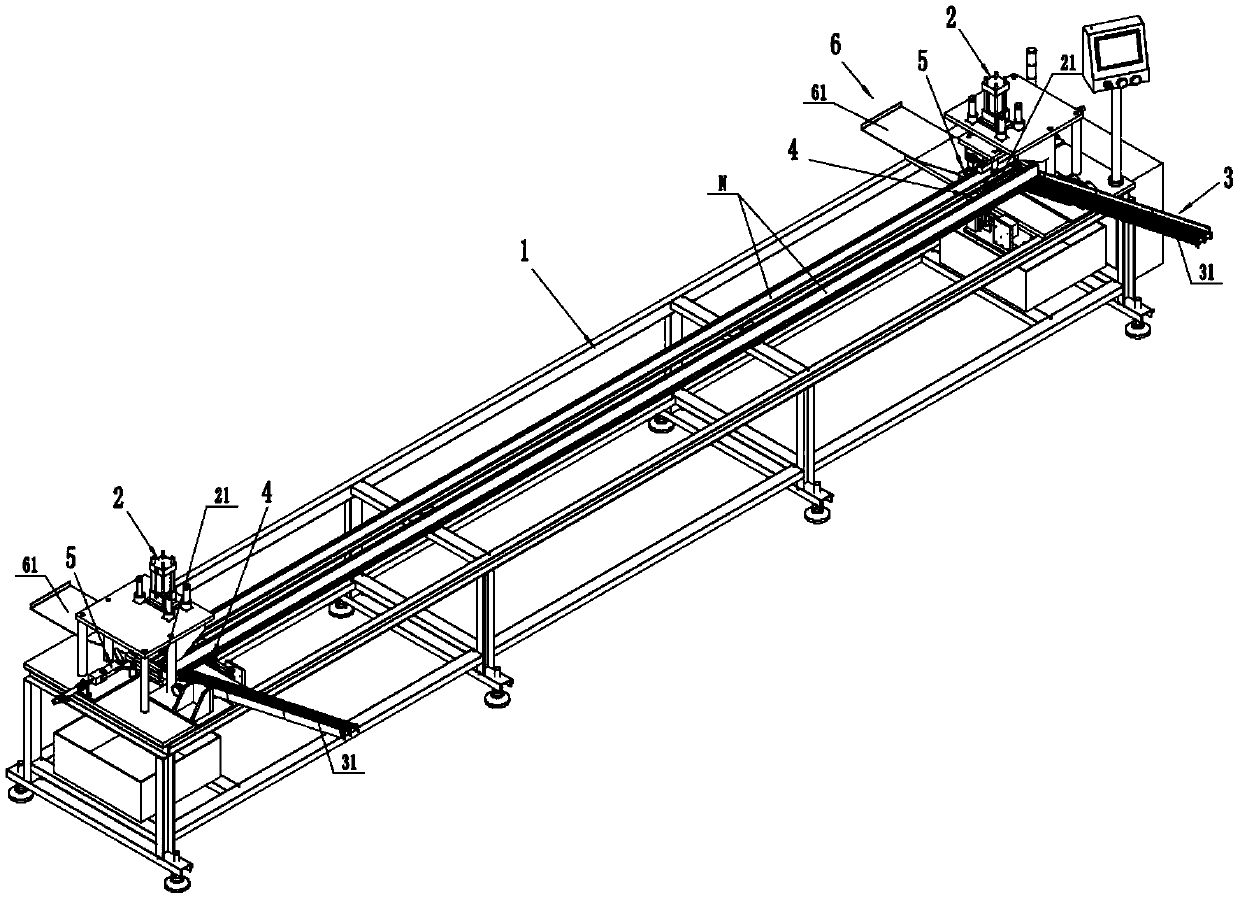
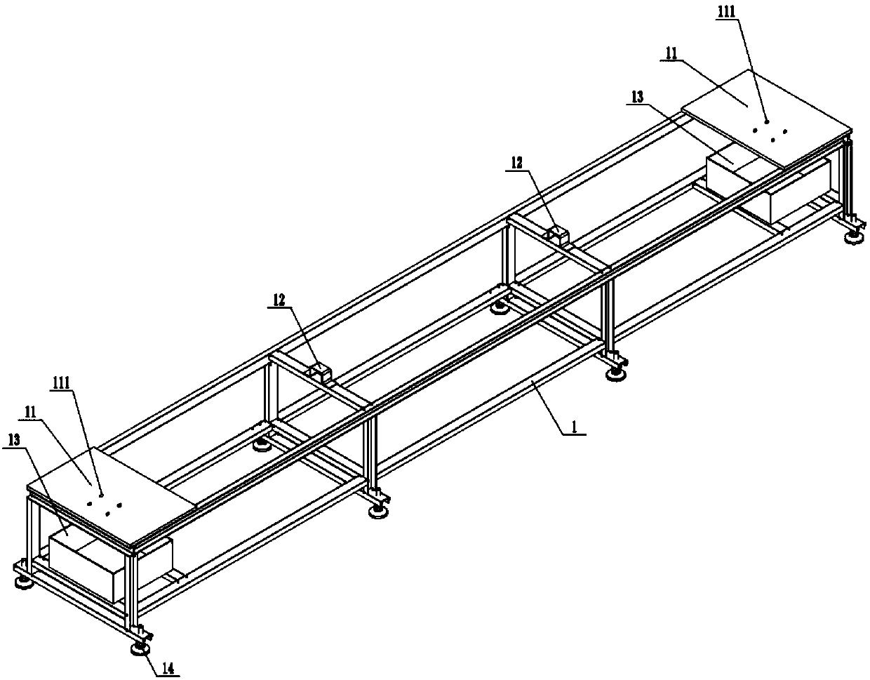
[0039] join Figure 1-16 Shown: a synchronous punching equipment at both ends of a several-shaped steel beam, which includes a frame 1, two punching mechanisms 2, a material rack 3, two discharging control mechanisms 4, and two blocking control mechanisms 5 And the material receiving frame 6, the material storing frame 3 and the material receiving frame 6 are respectively located on both sides of the width direction of the frame 1, and the two punching mechanisms 2 are located on both sides of the frame 1 along the length direction. Two discharge control mechanisms 4 are located on both sides of the frame 1 along the length direction, and the two discharge control mechanisms 4 are respectively used for synchronous blocking and synchronous release control at the two ends of the front several-shaped steel beam N; The control mechanism 5 is located on both side...


PUM


Abstract

The invention discloses n-shaped steel beam two-end synchronous punching equipment. The n-shaped steel beam two-end synchronous punching equipment comprises a machine frame, two punching mechanisms, amaterial placing frame, a material passing control mechanism, a material blocking control mechanism and a material receiving frame; the two punching mechanisms are arranged on the two sides of the machine frame in the length direction correspondingly; the material placing frame and the material receiving frame are positioned on the two sides of the machine frame in the width direction correspondingly; the material placing frame is provided with an inclined discharging support; the material passing control mechanism is used for performing blocking and passing control on an n-shaped steel beamat the lowest position of the inclined discharging support; the two ends of the n-shaped steel beam slide on the workbenches of the two punching mechanism correspondingly after the material passing control mechanism allows to pass; the material blocking control mechanism is used for performing positioning blocking during processing of the n-shaped steel beam on the machine frame and performing passing control after processing; and the material receiving frame is provided with a material receiving support. The n-shaped steel beam two-end synchronous punching equipment can perform punching processing on the two ends of the n-shaped steel beam simultaneously, can perform secondary positioning processing without turning 180 degrees and can realize automatic continuous production.

Description

technical field [0001] The invention belongs to a synchronous punching device at both ends of a several-shaped steel beam. Background technique [0002] see figure 1 , which is a type of steel beam (N) commonly used in buildings, bridges, tunnels and other projects. Both ends of the type steel beam (N) require punching and processing of four mounting holes (N-1) . And during existing punching processing, at first adopt four mounting holes (N-1) of an end of this several-shaped steel beam (N) to process on punching equipment, and because this several-shaped steel beam (N) The length is very long (usually ranging from 5-100m), and then the four mounting holes (N-1) at the other end are processed after turning 180° manually. It is heavy, very inconvenient to turn to processing, and there are problems such as complex production, high labor intensity, low production efficiency, and inability to automatically and continuously produce. Contents of the invention [0003] In or...

Claims


Application Information

Patent Timeline
Patent Type & Authority Patents(China)
IPC IPC(8): B21D28/36B21D28/34B21D43/20B21D43/16B21D43/00
CPCB21D28/243B21D28/36B21D43/003B21D43/16B21D43/20
Inventor 李运中
Owner 芜湖恒驰钢构有限公司
Why Eureka
Try Eureka