Robot used for cleaning airplanes

A robot and aircraft technology, applied in the field of aircraft cleaning equipment, can solve the problems of high work intensity, increased dirt friction, increased fuel consumption, etc., and achieve the effect of reasonable design, simple production, and avoiding tedious and dangerous effects

Inactive Publication Date: 2018-02-27
广西环游信息技术开发有限公司
View PDF0 Cites 4 Cited by
  • Summary
  • Abstract
  • Description
  • Claims
  • Application Information

AI Technical Summary

Problems solved by technology

[0002] Airplane is an important means of transportation for modern military or civilian use, and it is one of the most important inventions in the early 20th century. Because aircraft need frequent take-off and landing, entering and exiting the atmosphere, etc., the flying altitude ranges from 5,000 to 12,000 meters, and the span is relatively large. All kinds of dirt will accumulate on the surface of the aircraft. A large amount of dirt will not only affect the appearance of the aircraft, but also increase fuel consumption due to the increased friction of the dirt. As far as flight safety is concerned, cleaning is usually done manually now. The ground crew will use buckets, brushes, mops and other tools to climb up to a high place to clean the aircraft using work ladders. This cleaning method is not only labor-intensive, but also time-consuming and labor-intensive. , is cumbersome and complicated, so it is necessary to design a device that is convenient for cleaning the aircraft

Method used


Image

  • Robot used for cleaning airplanes
  • Robot used for cleaning airplanes
  • Robot used for cleaning airplanes

Examples


Embodiment Construction

[0014] Below in conjunction with accompanying drawing and specific embodiment the present invention is described in further detail:

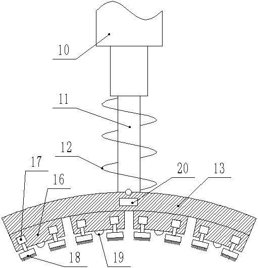
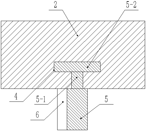
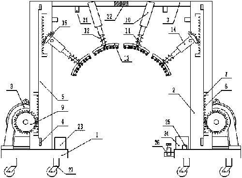
[0015] Such as figure 1 , figure 2 , image 3 As shown, a robot for cleaning an aircraft includes two bases 1, the upper end of the base 1 is vertically fixed with a riser 2, the upper end of the riser 2 is horizontally fixed with a cross bar 3, and the vertical plate 2 is vertically provided with a slide Slot 4, slide block 5-2 is slidably connected in described chute 4, and connection block 5-1 is fixed on the slide block 5-2, and the slide plate 5 that can slide vertically is fixed on the connection block 5-1, so The two sides of the sliding plate 5 are respectively provided with protruding teeth 6, the upper and lower ends of the protruding teeth 6 are respectively fixed with stoppers 7, the upper end of the base 1 is fixed with a deceleration motor 8, and the output shaft of the deceleration motor 8 is fixed with a The gear 9 with conve...


PUM


Abstract

The invention discloses a robot for cleaning aircraft, which comprises two bases, vertical boards on the bases, horizontal bars on the vertical boards, slide grooves on the vertical boards, sliders in the slide grooves, and connecting rods on the sliders. There is a sliding plate on the connecting block, there are convex teeth on both sides of the sliding plate, there are stoppers at both ends of the convex teeth, there is a deceleration motor on the base, there is a gear on the deceleration motor, there is a hydraulic rod A at the lower end of the cross bar, and the lower end of the hydraulic rod A There is a telescopic rod, the telescopic rod is covered with a spring, the lower end of the telescopic rod is hinged with an arc-shaped plate, the side end of the vertical plate is hinged with a hydraulic rod B, there is an arc-shaped tooth plate on the hydraulic rod B, and the lower end of the hydraulic rod B has a telescopic rod, arc-shaped There is a fixed block on the inner arc surface of the board, a motor inside the fixed block, a brush plate on the motor, a cleaning agent nozzle on the fixed block, and a pressure sensor inside the arc-shaped board. When cleaning, the cleaning liquid is sprayed from the cleaning nozzle through the water pump. The brush plate is cleaned more cleanly, and the high-pressure water gun nozzle is used for washing, which saves time and effort, is efficient and fast, and eliminates the tedious and dangerous manual cleaning.

Description

technical field [0001] The invention relates to the technical field of aircraft cleaning equipment, in particular to a robot for cleaning aircraft. Background technique [0002] Airplane is an important means of transportation for modern military or civilian use, and it is one of the most important inventions in the early 20th century. Because aircraft need frequent take-off and landing, entering and exiting the atmosphere, etc., the flying altitude ranges from 5,000 to 12,000 meters, and the span is relatively large. All kinds of dirt will accumulate on the surface of the aircraft. A large amount of dirt will not only affect the appearance of the aircraft, but also increase fuel consumption due to the increased friction of the dirt. As far as flight safety is concerned, cleaning is usually done manually now. The ground crew will use buckets, brushes, mops and other tools to climb up to a high place to clean the aircraft using work ladders. This cleaning method is not only l...

Claims


Application Information

Patent Timeline
Patent Type & Authority Applications(China)
IPC IPC(8): B64F5/30
CPCB64F5/30
Inventor 郭晓非
Owner 广西环游信息技术开发有限公司
Why Eureka
Try Eureka