Ultrasonic liquid level measurement method and device

A liquid level measurement device and liquid level measurement technology are applied in the direction of measuring devices, liquid/fluid solid measurement, and lubrication indicating devices, etc., which can solve problems such as large fluctuations in liquid levels, mist entrainment, and difficulties in accurate liquid level measurement. Achieve the effect of simple and convenient operation and stable detection

Inactive Publication Date: 2018-02-27
王涵青
View PDF0 Cites 5 Cited by
  • Summary
  • Abstract
  • Description
  • Claims
  • Application Information

AI Technical Summary

Problems solved by technology

However, in the gas-liquid system, due to the entry and exit of gas / liquid materials, gas bubbling, gas jets, etc., the liquid level fluctuates greatly or mist entrainment occurs, which brings great challenges to the accurate measurement of the liquid level. difficulty

Method used


Image

  • Ultrasonic liquid level measurement method and device
  • Ultrasonic liquid level measurement method and device
  • Ultrasonic liquid level measurement method and device

Examples


Embodiment 1

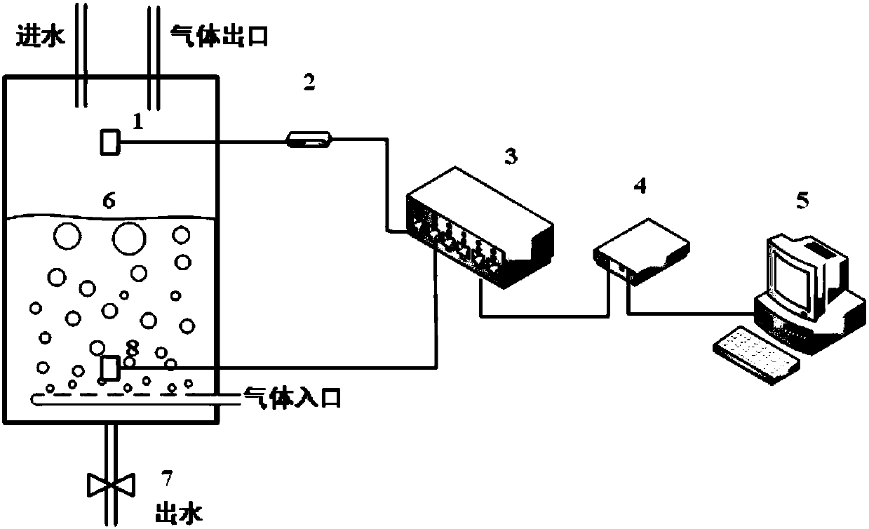
[0033] Embodiment 1: Static liquid level measurement of gas-liquid bubbling device

[0034] The liquid used in the experiment is water, which can be injected from the upper water injection port or flow out from the lower valve, thereby changing the liquid level in the gas-liquid bubbling device 6 . The acoustic signal measured by the receiving probe 1 is converted into an electrical signal and then recorded by the acquisition card 4 and the computer 5 . The transmitting probe 8 generates a 200kHz square wave sound signal, and the receiving probe 1 has a sampling frequency of 500kHz.

[0035] The specific experimental plan is as follows:

[0036] (1) During the experiment, the transmitting probe 8 is located below the gas-liquid bubbling device 6, 50 mm away from the gas inlet, and the receiving probe 1 is placed above the gas-liquid bubbling device 6, and the distance from the transmitting probe 8 is 400 mm

[0037] (2) The liquid level starts from the bottom of the gas-liqu...

Embodiment 2

[0042] Example 2: Dynamic liquid level measurement of gas-liquid bubbling device

[0043] The liquid used in the experiment is water, which can be injected from the upper water injection port or flow out from the lower valve, thereby changing the liquid level in the gas-liquid bubbling device 6 . The acoustic signal measured by the receiving probe 1 is converted into an electrical signal and then recorded by the acquisition card 4 and the computer 5 . The transmitting probe 8 generates a 175kHz square wave signal, and the receiving probe 1 has a sampling frequency of 500kHz.

[0044] (1) Close the water outlet valve 7 in the experiment, inject liquid from the liquid injection port on the top of the gas-liquid bubbling device 6, the liquid level height increases by 50mm per minute, and feed a flow of 20 cubic meters per hour into the gas-liquid bubbling device The air, the liquid level increases continuously from 0 to the receiving probe 1, and the receiving probe 1 continuous...


PUM


Abstract

The invention discloses an ultrasonic liquid level measurement method and device, comprising: step 1, installing the transmitting probe of the signal transmitting system on the lower part of the side wall of the gas-liquid bubbling device, converting the signal generated by the signal generator into an ultrasonic signal; 2. Install the receiving probe of the signal acquisition system on the side wall of the gas-liquid bubbling device to receive the ultrasonic signal, convert the ultrasonic signal into an electrical signal and transmit it to the acquisition card and computer; step 3, according to the principle of amplitude attenuation of the ultrasonic signal And the principle of shock absorption, establish the ultrasonic damping attenuation liquid level detection model; step 4, according to the ultrasonic damping attenuation liquid level detection model, establish the correlation between the received signal and the liquid level, and detect the liquid level. The invention can adapt to various measurement environments such as liquid level fluctuations, mist entrainment, complicated internal components, etc., and can accurately and stably detect the liquid level.

Description

technical field [0001] The invention relates to the field of liquid level detection, in particular to an ultrasonic liquid level measurement method and device. Background technique [0002] The liquid level height is an important parameter of household steamers, fresh aquatic product transportation tanks, liquid storage tanks, gas-liquid bubble towers and other living and production devices. The change rate of the liquid level height can be used to characterize the smoothness and stability of the discharge , Play an important role in the operation of liquid storage devices and gas-liquid reaction systems. However, in the gas-liquid system, due to the entry and exit of gas / liquid materials, gas bubbling, gas jets, etc., the liquid level fluctuates greatly or mist entrainment occurs, which brings great challenges to the accurate measurement of the liquid level. difficulty. [0003] Conventional static liquid level can be accurately measured by methods such as static pressure...

Claims


Application Information

Patent Timeline
Patent Type & Authority Applications(China)
IPC IPC(8): G01F23/296
CPCG01F23/2965
Inventor 王涵青
Owner 王涵青
Why Eureka
Try Eureka