Insulation operating platform for isolation switch

A technology for operating platforms and isolating switches, applied to switchgear, electrical components, etc., can solve the problems of ineffective protection, time-consuming and labor-intensive, frequent movement of insulating operating platforms, etc., to save wasted time and reduce labor intensity Effect

Inactive Publication Date: 2018-02-27
PANZHIHUA POWER SUPPLY COMPANY STATE GRID SICHUAN ELECTRIC POWER
View PDF5 Cites 0 Cited by
  • Summary
  • Abstract
  • Description
  • Claims
  • Application Information

AI Technical Summary

Problems solved by technology

[0002] With the construction and development of the power grid, the main equipment in the system has increased rapidly, and users have higher and higher requirements for power supply reliability and quality. This has brought a very severe test to the substation maintenance personnel. While requiring the quality of maintenance work, it is also necessary to ensure the reliability of power supply and the efficiency of power consumption, resulting in a contradiction between safety and efficiency
The original insulating operation platform has a single function. When repairing circuit breakers, isolating switches and other equipment outdoors, it is necessary to complete each phase of maintenance. The operator needs to disassemble the insulating operating platform and move it to another phase for operation. As the maintenance process continues, the original insulation operation platform moves frequently, which increases the labor load of the operators. It is not only time-consuming and laborious, but also the safety performance cannot be guaranteed, which cannot meet the current grid equipment maintenance. need

Method used


Image

  • Insulation operating platform for isolation switch
  • Insulation operating platform for isolation switch
  • Insulation operating platform for isolation switch

Examples


Embodiment 1

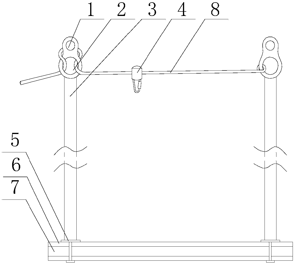
[0025] Such as figure 1As shown, the present embodiment includes two bases 5, an insulating support rod 3 is fixed on the upper end surface of each of the bases 5, and a fixed block is arranged on the upper end of the support rod 3, along the axis of the support rod 3 A small hole 1 and a large hole 2 are sequentially opened on the fixed block from top to bottom. The axis of the small hole 1 is parallel to the axis of the large hole 2, and a safety rope 8 is also included. The initial end of the safety rope 8 is connected to a The fixed block is connected, and after the end of the safety rope 8 passes through the inside of the large hole 2 on the other fixed block, it is wound on the outer wall of the small hole 1 for half a circle and then continues to extend outward after passing through the large hole 2 again, and A rope grab 4 is provided on the safety rope 8 , and the rope grab 4 is located between the two support rods 3 . In view of the defects in the protective measure...

Embodiment 2

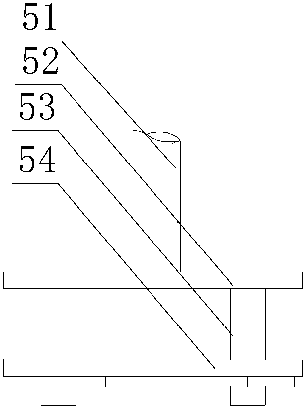
[0028] Such as Figure 1~2 As shown, the base 5 in this embodiment includes a sleeve 51 and an upper plate 52 and a lower plate 54 parallel to each other, the sleeve 51 is fixed on the upper surface of the upper plate 52, and the lower end of the support rod 3 is placed on the In the sleeve 51, the upper plate 52 and the lower plate 54 are connected by bolts 53. Further, since the load-bearing part of the base 5 is an I-shaped channel steel 6, and utilizing the particularity of the shape of the channel steel 6, the upper plate 52 and the lower plate 54 are respectively placed on the upper surface and the lower surface of the channel steel 6, Then the upper plate 52 and the lower plate 54 are connected and fixed by bolts 53 , and the sleeve 51 is fixed on the upper surface of the upper plate 52 to provide effective support for the support rod 3 .

[0029] Preferably, three screw holes in a triangular distribution are provided on the upper plate 52 and the lower plate 54, and t...

Embodiment 3

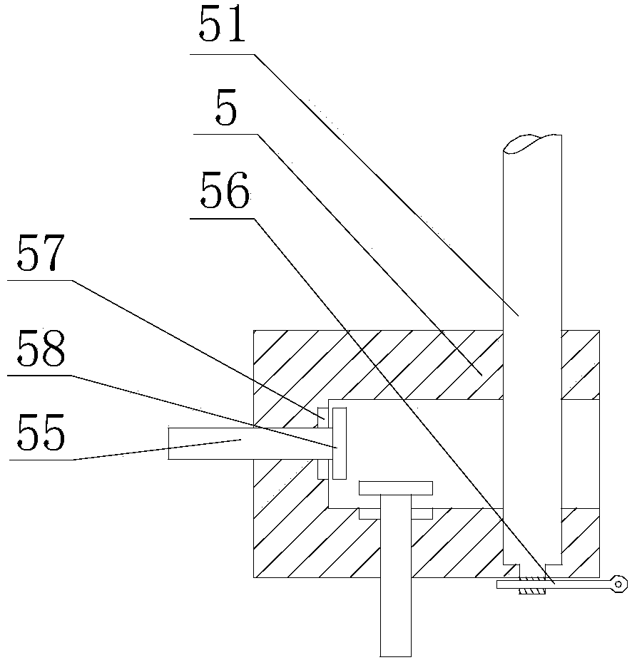
[0031] Such as figure 1 , 3 As shown, the base 5 in this embodiment includes a U-shaped body and a sleeve 51, the opening direction of the body is parallel to the horizontal direction, through holes and blind holes are respectively provided on the two horizontal sections of the body, and the sleeve The lower end of 51 enters the blind hole after passing through the through hole, and the lower end of the support rod 3 is placed in the sleeve 51 . Further, the base 5 includes a body and a sleeve 51, wherein the body is U-shaped, and its opening direction is parallel to the horizontal direction, so that the body can pass through the channel steel 6 transversely, ensuring that the upper and lower surfaces of the channel steel 6 are aligned with the U-shaped area of ​​the body. contact, and the through holes and blind holes provided on the horizontal section of the body can facilitate the rapid insertion of the sleeve 51 and ensure that the sleeve 51 is integrated with the base 5 ...


PUM


Abstract

The invention discloses an insulation operating platform for an isolation switch. The insulation operating platform comprises two bases. A supporting rod is fixed to the upper end of each base, and afixing block is arranged at the upper end of each supporting rod. Small holes and large holes are sequentially formed in the fixed blocks in the axes of the supporting rods from top to bottom. The axes of the small holes are parallel to the axes of the large holes. The initial end of a safety rope is connected to one fixing block; the end of the safety rope passes through the inside of the large holes on the other fixing block, is wound half a turn on the outer side walls of the small holes, and then passes through the large holes again and continues to extend outwards. An operator can adjusthis / her position in time according to the change of an inspection station to solve the inconvenience of fixed-point positioning and maintenance. At the same time, in the event of an accident, the operator can be quickly lowered to the ground by releasing the fastening state at the end of the safety rope to prevent the operator from being left in a suspended state after the occurrence of the danger, the emergency time is shortened and the construction safety of the operator is ensured to the maximum extent.

Description

technical field [0001] The invention relates to the field of power equipment maintenance, in particular to an insulating operation platform for an isolating switch. Background technique [0002] With the construction and development of the power grid, the main equipment in the system has increased rapidly, and users have higher and higher requirements for power supply reliability and quality. This has brought a very severe test to the substation maintenance personnel. While requiring the quality of maintenance work, it is also necessary to ensure the reliability of power supply and the efficiency of power consumption, resulting in a contradiction between safety and efficiency. The original insulating operation platform has a single function. When repairing circuit breakers, isolating switches and other equipment outdoors, it is necessary to complete each phase of maintenance. The operator needs to disassemble the insulating operating platform and move it to another phase for...

Claims


Application Information

Patent Timeline
Patent Type & Authority Applications(China)
IPC IPC(8): H02B3/00
CPCH02B3/00
Inventor 徐守才
Owner PANZHIHUA POWER SUPPLY COMPANY STATE GRID SICHUAN ELECTRIC POWER
Why Eureka
Try Eureka