Continuous coating machine and continuous coating method with continuous coating machine

A coating machine and coating technology, applied in the field of coating machine equipment and coating, continuous coating machine, and continuous coating, can solve the problems of low production efficiency, long time consumption, and large energy consumption, and achieve Increased production efficiency, shorter time consumption, and lower energy consumption

Active Publication Date: 2018-03-02
NANO PHARM TECH MACHINERY EQUIP
View PDF7 Cites 8 Cited by
  • Summary
  • Abstract
  • Description
  • Claims
  • Application Information

AI Technical Summary

Problems solved by technology

[0004] The purpose of the present invention is to solve the problems of long time consumption, high energy consumption and low production efficiency when the existing coating machine coats large quantities of materials

Method used


Image

  • Continuous coating machine and continuous coating method with continuous coating machine
  • Continuous coating machine and continuous coating method with continuous coating machine
  • Continuous coating machine and continuous coating method with continuous coating machine

Examples


specific Embodiment approach 1

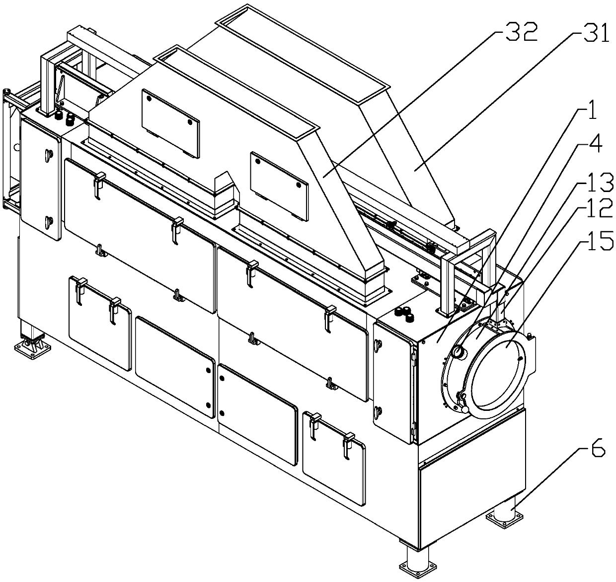
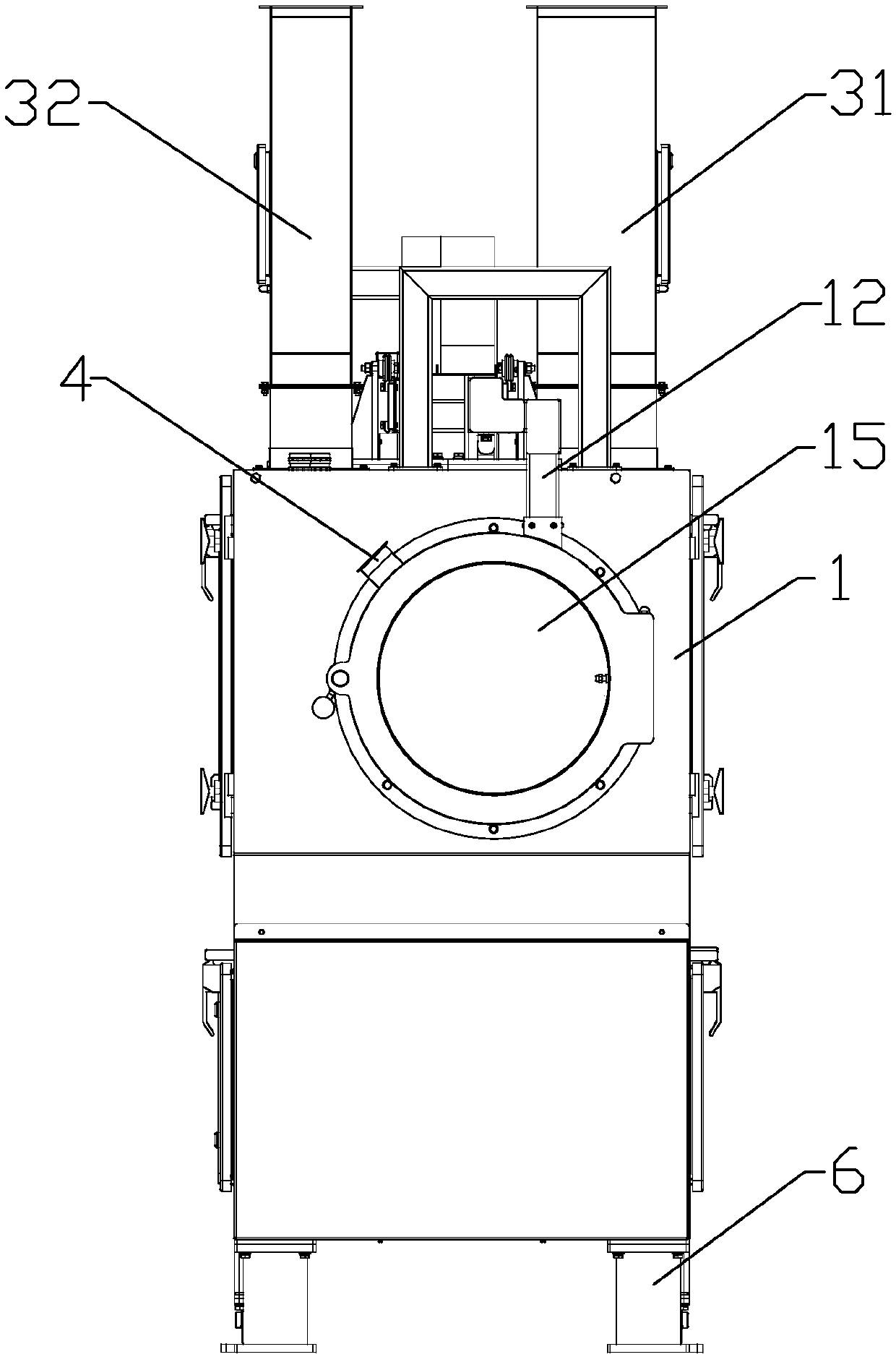
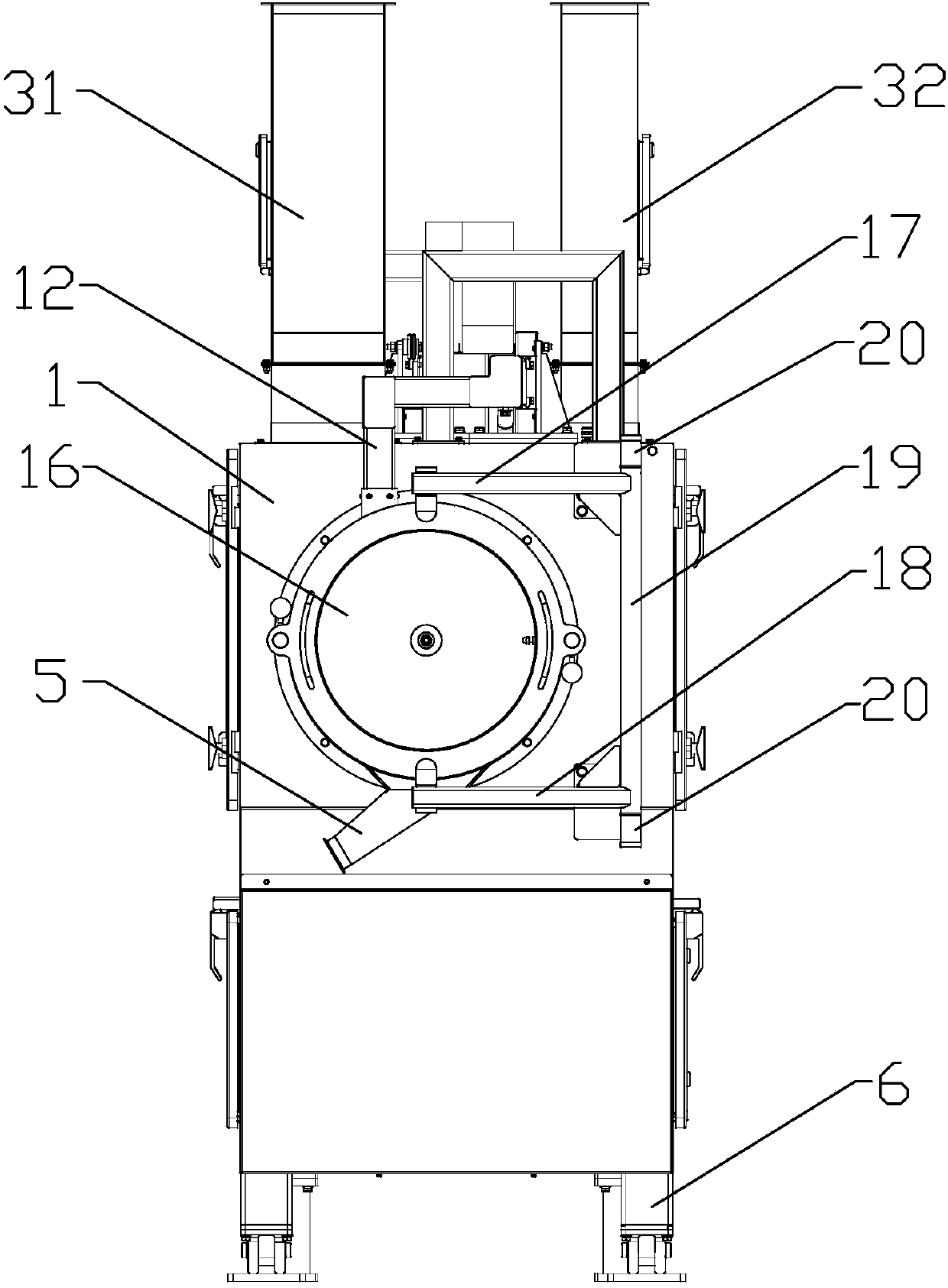
[0053] Specific implementation mode one: combine Figure 1-Figure 4 Describe this embodiment, a continuous coating machine of this embodiment, including a machine body 1, a coating drum 2, and a motor 3 that drives the coating drum to rotate along the axis, between the motor and the coating drum The transmission mode of the coating can be belt transmission, gear transmission or other suitable transmission modes. Usually, the rotation direction of the coating drum is clockwise during coating production. Continuous coating machine also comprises feed pipe 4, discharge pipe 5, support leg 6 and cylinder 7, and described coating drum is the elongated cylindrical shape of two ends opening, and generally, the length of described coating drum is not Less than 1.6m, diameter not less than 0.27m. The coating drum is horizontally and rotatably sealed and installed in the body, the wall of the coating drum is densely covered with through holes, and the front end of the body is provided ...

specific Embodiment approach 2

[0057] Specific implementation mode two: combination Figure 4 , Figure 8 , Figure 9 and Figure 10 To illustrate this embodiment, the continuous coating machine of this embodiment also includes a plurality of feeders 8, which are elongated and generally slightly shorter than the coating drum. The cross-section is semicircular, and the feeder is fixedly installed on the inner wall of the coating drum along the axial direction of the coating drum, and the arc-shaped outer arc surface of the feeder points to the coating drum The axis, usually the number of the auger is six, evenly distributed along the radial direction of the coating drum. The setting of the feeder helps to turn over the material during the rotation of the coating drum, so that the material can fully contact with the spray liquid of the spray gun, and improve the coating effect and coating efficiency. The design of the shape of the feeder, The material to be lifted or shifted can slide or roll smoothly on ...

specific Embodiment approach 3

[0058] Specific implementation mode three: combination Figure 1-Figure 4 Illustrate this embodiment, the continuous coating machine of this embodiment also includes spray gun mounting frame 9 and spray gun 10, and described spray gun mounting frame is from the front end and / or rear end of described machine body along the axial direction of described coating drum. Stretching into the coating drum from outside to inside, a plurality of spray guns are installed at equal intervals from front to back on the spray gun mounting frame, and the spray gun mounting frame is divided into a plurality of sequentially connected and identical spray gun areas from front to back, At least one spray gun is included in each spray gun area, and each spray gun is controlled independently. The liquid is usually in the shape of a cone, so that the drug can be sprayed to the surface of the material more uniformly, and the coating effect can be better achieved. Generally, the spray gun installation f...


PUM

PropertyMeasurementUnit
lengthaaaaaaaaaa
diameteraaaaaaaaaa

Abstract

The invention provides a continuous coating machine and a continuous coating method with the continuous coating machine, and relates to a coating machine and a coating method. In order to solve the problems that when a conventional coating machine is used for coating production of massive materials, the time consumption is high, the energy consumption is high, and the production efficiency is nothigh, the invention provides the continuous coating machine. A coating roller is a slab-sided cylinder with two opened ends, and is horizontally mounted in a machine body in a rotating and sealing manner, and through holes are densely distributed in the wall of the coating roller; a feed pipe is arranged at the front end of the machine body, and a discharge pipe is arranged at the rear end of themachine body; and support legs are mounted at four corners of the bottom end of the machine body, and an air cylinder capable of controlling the lifting of the machine body and the coating roller is vertically mounted in two support legs at the front end of the machine body. The coating roller is used for continuously feeding and discharging materials, in the process that the materials advance tothe outlet of the coating roller from the inlet of the coating roller, the coating is completed, and continuous coating production of the massive materials is realized; and besides, the production energy consumption is rationalized, zero consumption during production is realized, and the continuous coating machine is used for coating the materials.

Description

technical field [0001] The invention relates to a coating machine equipment and a coating method, in particular to a continuous coating machine and a continuous coating method using the continuous coating machine, belonging to the fields of pharmaceutical, food and chemical equipment. Background technique [0002] The coating machines in the prior art all adopt the batch coating mode, that is, a fixed batch of materials is transported to the coating drum for coating, and the coated materials are discharged from the coating drum, and then the next batch of materials is Transport to the coating drum for coating, so repeatedly. When the amount of material to be coated is relatively large, it needs to be divided into multiple batches for coating, which takes a long time, consumes a lot of energy, and the production efficiency is not high. The use of multiple coating machines for coating production at the same time, although it can reduce production time and improve production e...

Claims


Application Information

Patent Timeline
Patent Type & Authority Applications(China)
IPC IPC(8): A23P20/18A61J3/00
CPCA23P20/18A61J3/005
Inventor 王孟刚
Owner NANO PHARM TECH MACHINERY EQUIP
Why Eureka
Try Eureka