
Battery module centralized storage and charging-discharging box system capable of ensuring fire fighting safety

A battery module and centralized technology, which is applied to battery pack components, secondary batteries, secondary battery repair/maintenance, etc., can solve problems such as inability to completely extinguish fires, threaten the safety of surrounding warehouses, and achieve diversified composition forms , Easy to install, compact structure

Pending Publication Date: 2018-03-02
重庆聚陆新能源有限公司
View PDF5 Cites 10 Cited by
  • Summary
  • Abstract
  • Description
  • Claims
  • Application Information

AI Technical Summary

Problems solved by technology

Since most lithium-ion batteries catch fire, in addition to completely submerging or burying them with water or sand, conventional fire extinguishing media can only suppress the flames but cannot completely extinguish the fire
In the existing technology, most of the charging circuits are immediately shut off after a fire is discovered, and the fire is directly extinguished in the charging compartment. In the case of incomplete or untimely fire extinguishing, the safety of the surrounding positions will be threatened.

Method used


Image

  • Battery module centralized storage and charging-discharging box system capable of ensuring fire fighting safety
  • Battery module centralized storage and charging-discharging box system capable of ensuring fire fighting safety
  • Battery module centralized storage and charging-discharging box system capable of ensuring fire fighting safety

Examples


Embodiment 1

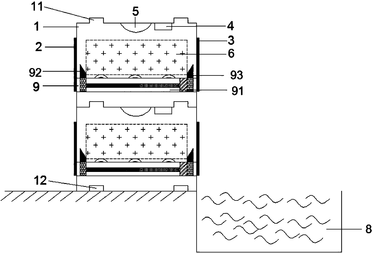
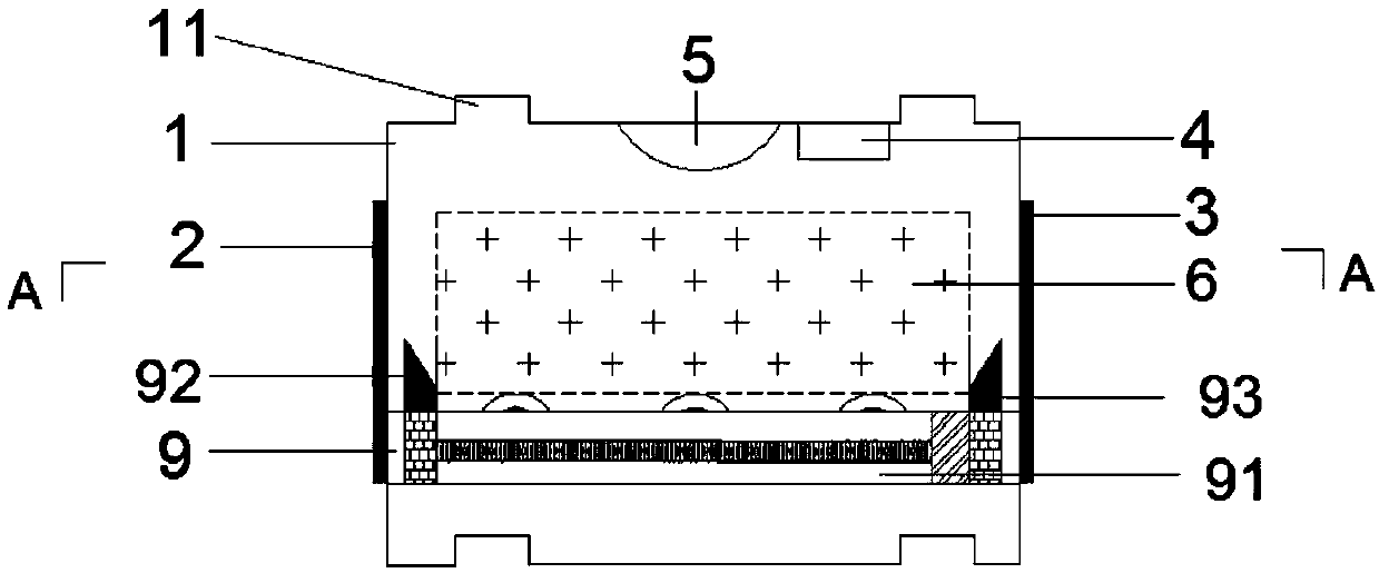
[0039] Such as Figure 1~2 , a battery module centralized storage and charging and discharging box system to ensure fire safety, including a box system and a water tank 8 arranged on one side of the box system, the box system includes a box 1, located at the front and back of the box Outbound door 2 at both ends, fire door 3, composite sensor 4 and fire sprinkler 5 at the top inside the box, a two-way motion mechanism that can push the battery 6 out of the outbound door 2 and fire door 3 inside the box, and can The control module 7 that receives the signal of the composite sensor 4 and controls the two-way motion mechanism and the fire sprinkler 5; the water tank 8 is located on the outer side of the fire door 3. Among them, the two-way motion mechanism and the control module are in Figure 1~2 not shown in

[0040] Further, the top of the box 1 used in this embodiment is provided with a convex male end 11, and the bottom is provided with a concave female end 12 matching it....

Embodiment 2

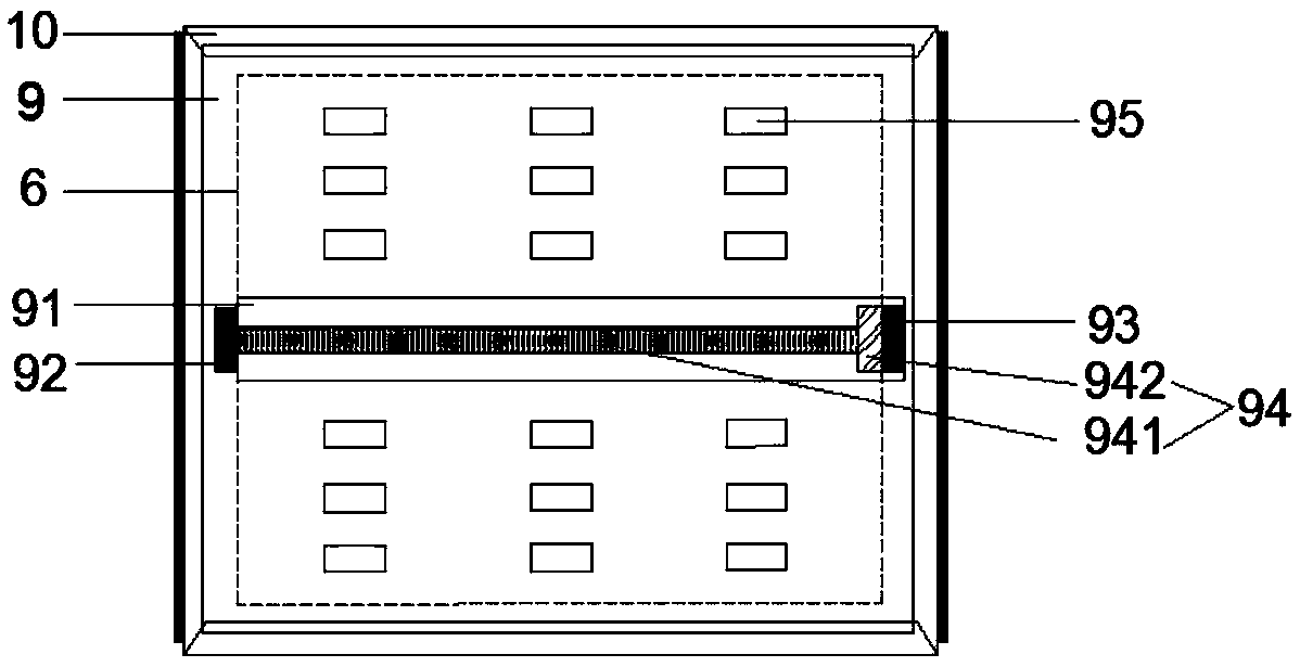
[0046] The difference from Embodiment 1 is that the two-way motion mechanism used in this embodiment includes a tray 9 for placing the battery 6 inside the box, and a chute 10 for sliding the tray 9 on the side wall of the box; the tray 9 A fire-fighting slideway 91 is provided in the thickness direction, and a fire-fighting pin 92 is provided at one end of the fire-fighting slideway 91 close to the delivery door 2, and a positioning pin 93 is provided at one end close to the fire-fighting door 3; The driving mechanism 94 on the top, the driving mechanism 94 is connected with the fire fighting pin 92 and can drive it to move along the fire fighting slide 91; the positioning pin 93 and the driving mechanism 94 are both connected with the control module 7 and controlled by it.

[0047] Of course, those skilled in the art should know that the two-way motion mechanism can also be other power mechanisms that can realize the normal discharge of batteries and emergency fire protection...

Embodiment 3

[0054] The difference from Embodiment 2 is that the driving mechanism 94 used in this embodiment is a ball screw mechanism, which includes a lead screw 941 arranged in the fire slide 91, and a limit base 942. One end of the lead screw 941 is connected to the The fire pin 92 is connected, and the other end is inserted into the limit base 942 .

[0055] The normal charge and discharge / storage and normal take-out of the battery are the same as the second embodiment, and will not be repeated here.

[0056] When the battery is out of the warehouse for emergency fire fighting, the ball screw mechanism drives the fire pin 92 to move toward the fire door 3 along the leading screw 941, and the battery is released and dropped into the water tank. The limit base 942 can ensure the stability of the fire-fighting pin moving along the lead screw, and also plays a role in limiting the extreme movement position of the fire-fighting pin 92 .

[0057] Of course, those skilled in the art should...


PUM


Abstract

The present invention discloses a battery module centralized storage and charging-discharging box system capable of ensuring fire fighting safety. The battery module centralized storage and charging-discharging box system is used in the field of energy storage systems and new energy vehicle batteries, and comprises a box system formed by combining one or a plurality of boxes, and a water tank on one side of the box system, wherein the box comprises an outlet door, a fire fighting door, a composite sensor, a fire fighting spraying nozzle and a two-way movement mechanism positioned inside the box and capable of pushing a battery out of the outlet door and the fire fighting door. In the prior art, when the individual box in the existing box system is on fire, the sub-bin sprays the fire extinguishing gas, and the fire on the battery in the box cannot be completely extinguished. A purpose of the present invention is mainly to solve the problem in the prior art so as to prevent the disasterexpansion caused by the spreading of the fire on other boxes. According to the present invention, with the battery module centralized storage and charging-discharging box system, the fire condition can be timely detected, and the battery can be pushed out of the fire fighting door until the battery is immersed in the water tank, such that the safety of other boxes in the box system can be ensured, and the absolute safety and reliability of the charging station can be achieved; and the taking-placing operation of the normal battery module is performed at the door side of the box, such that f the door to the warehouse, will not be interference by the sink.

Description

technical field [0001] The invention belongs to the field of energy storage systems and new energy vehicle batteries, and specifically relates to a battery module centralized storage and charging and discharging box system for ensuring fire safety. Background technique [0002] With the increasing popularity of new energy vehicles, the share of electric vehicles in the automotive market has been increasing, and there is a trend of continuing to expand applications. As an important part of electric vehicles, power batteries are the energy source of electric vehicles, and the charging and energy storage of batteries is an extremely important part of the development of electric vehicles. At present, it is common to use containers to store energy in battery packs and to charge spare batteries for battery replacement. Many of these solutions use a multi-position design, and the battery modules in each position are charged / discharged independently. [0003] Fire safety is the mos...

Claims


Application Information

Patent Timeline
Patent Type & Authority Applications(China)
IPC IPC(8): H01M2/10H01M10/42H01M10/48H01M50/204
CPCH01M10/4207H01M10/425H01M10/482H01M50/20Y02E60/10
Inventor 陆帅
Owner 重庆聚陆新能源有限公司
Learn More