Split type four-roller corrugated plate rolling machine

A plate rolling machine, split-type technology, applied in the direction of presses, manufacturing tools, push-out equipment, etc., can solve the problems of high difficulty in assembly of four-roll plate rolling machines, difficulty in ensuring welding accuracy of the frame, and difficulty in removing curved plates. , to achieve the effects of compact structure, simple and ingenious structural design, and improved assembly speed

Active Publication Date: 2018-03-06
ANHUI DEXI DHI TECH
View PDF19 Cites 0 Cited by
  • Summary
  • Abstract
  • Description
  • Claims
  • Application Information

AI Technical Summary

Problems solved by technology

[0009] The invention provides a split-type four-roller corrugated plate rolling machine, aiming to solve the problems of high assembly difficulty and low efficiency of the existing four-roller plate rolling machine, and difficulty in guaranteeing the welding accuracy of the frame supporting each roll
[0010] On the basis of the existing structure, the plate rolling machine of the present invention also adds a supporting device, which can effectively solve the problem that the curved plate is difficult to remove after the existing plate rolling machine is rolled

Method used


Image

  • Split type four-roller corrugated plate rolling machine
  • Split type four-roller corrugated plate rolling machine
  • Split type four-roller corrugated plate rolling machine

Examples


Embodiment 1

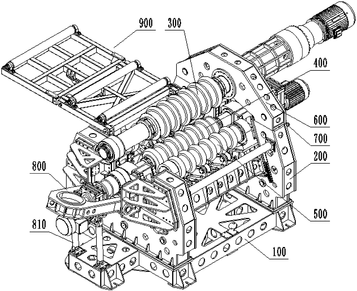
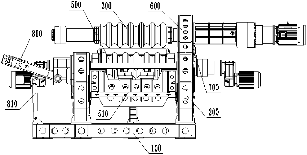
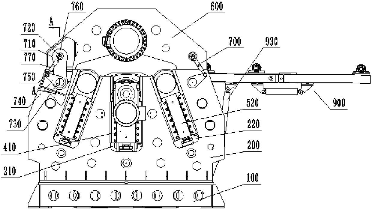
[0069] like figure 1 , figure 2 , image 3 As shown, a split-type four-roller corrugated plate bending machine in this embodiment mainly includes a base 100, a pair of racks 200, an upper roll 300, a lower roll 400, a pair of side rolls 500, a top frame 600 and tensioning Agency 700. Wherein, a pair of frame 200 is arranged on the opposite two sides on the base 100, and the base 100 and the frame 200 are welded by plates, and there are a plurality of stiffener plates inside, to enhance their strength, and the frame 200 passes through The bolts are fixed on the base 100, and the two ends of the lower roller 400 are respectively supported on the frame 200 by a lower roller oil cylinder 410. A side roller oil cylinder 520 is also supported and arranged on the frame 200 .

[0070] In the traditional plate rolling machine, the upper roll 300 is also directly installed on the frame. Because the pressure of the working roll of the plate rolling machine is very high, the support ...

Embodiment 2

[0076] In this embodiment, a split type four-roller corrugated plate bending machine is designed on the basis of Embodiment 1 to optimize the installation form of each roll. In the traditional plate rolling machine, each roller is driven by an oil cylinder, that is, the oil cylinder is connected to the slider, and the two ends of the roller are installed on the slider. In order to ensure the stability of the up and down movement of each roller, the supporting surface of the slider has a certain length requirement. As a result, the height of the rack is relatively high, the weight of the whole machine is relatively heavy, and the manufacturing cost is also high.

[0077] To solve this problem, as image 3 As shown, in the present embodiment, a lower roller groove 210 and side roller grooves 220 located on both sides of the lower roller groove 210 are provided on the frame 200, and the lower roller cylinder 410 and the side roller cylinder 520 are respectively arranged in the lo...

Embodiment 3

[0083] A split-type four-roller corrugated plate bending machine in this embodiment is further improved on the basis of Embodiment 1 or 2, so as to facilitate the removal of rolled parts.

[0084] When rolling a full-round pipe, the overturning cylinder 810 is used to drive the overturning bracket 800 to overturn downwards, so that one end of the upper roller 300 is opened, so that the workpiece can be removed; while when rolling a curved plate, generally For convenience and quickness, the workpiece is directly removed from the discharge side; however, since the arc-shaped plate has no reliable force point and is easy to slide, after the rolling is completed, if the lower roller cylinder 410 and the side roller cylinder 520 are directly driven When the lower roller 400 and the side roller 500 go down to release the workpiece, the workpiece will slide directly between the upper roller 300 and the lower roller 400, and it is difficult to take it out, or the rollers continue to ro...


PUM


Abstract

The invention discloses a split type four-roller corrugated plate rolling machine and belongs to the technical field of plate rolling machines. The device comprises a pair of racks, an upper roller, atop frame and a tensioning mechanism, wherein one end of the upper roller is installed on one machine frame through a turnover support, and the other end is mounted on the other machine frame throughthe top frame. The two ends of the top frame are detachably connected with the machine frame through a tensioning mechanism respectively. The tensioning mechanism comprises a tensioning connecting rod, a swinging connecting rod and a locking screw sleeve, wherein one end of the tensioning connecting rod is connected with the top frame through a top frame pin shaft, the other end of the upper screw rod is connected with the machine frame through an eccentric locking pin shaft, and the top frame pin shaft is connected with one end of the upper screw rod. One end of the swing connecting rod is connected with the eccentric locking pin shaft, and the other end of the swing connecting rod is connected with one end of the lower screw rod. The two ends of the locking screw sleeve are provided with forward screw holes and reverse screw holes, are respectively in threaded connection with the other end of the upper screw rod and the other end of the lower screw rod. The racks of a plate rollingmachine adopt split structure design, so that the assembly of the plate rolling machine is greatly facilitated, and the assembling speed is improved by 3-4 times compared with that of an existing plate rolling machine.

Description

technical field [0001] The invention belongs to the technical field of plate rolling machines, and more specifically relates to a split type four-roller corrugated plate rolling machine. Background technique [0002] Plate rolling machine (also called round rolling machine) is a machine tool used for continuous point bending of sheet metal. According to its structure, it can be divided into two-roll plate rolling machine, three-roll plate rolling machine and four-roll plate rolling machine. Two-roll plate rolling machines mostly process smaller-sized material plates, while three-roll and four-roll plate rolling machines are usually used to process large material plates, such as marine steel plates. [0003] The working principle of the three-roll plate rolling machine is to pass the flat plastic metal plate between three work rolls (two lower rolls and one upper roll), and to make the metal plate pass through the Multi-pass continuous bending, resulting in permanent plastic...

Claims


Application Information

Patent Timeline
Patent Type & Authority Applications(China)
IPC IPC(8): B21D5/08B21D5/12B21D45/02B30B15/16
CPCB21D5/083B21D5/12B21D45/02B30B15/166
Inventor 吴善普吴善照
Owner ANHUI DEXI DHI TECH
Why Eureka
Try Eureka