Digital tube film pasting and cutting equipment

A technology of cutting equipment and digital tubes, which is applied in metal processing, packaging, instruments, etc., can solve the problems of lower production efficiency, poor operation, and film sticking work changes, and achieve the effects of improving production efficiency, ensuring film quality, and improving precision

Pending Publication Date: 2018-03-06
JIANGMEN PENGJIANG AREA JINGHUI ELECTRONICS SCI & TECH CO LTD
View PDF5 Cites 3 Cited by
  • Summary
  • Abstract
  • Description
  • Claims
  • Application Information

AI Technical Summary

Problems solved by technology

After the above steps are completed, the surface of the nixie tube will be pasted with a film. The traditional method of pasting the film is done individually. The disadvantage of doing it alone is that it is not only low in efficiency, but also difficult to operate. In the prior art, the patent number is ZL201420650314.1zhong. A nixie tube electric film sticking equipment, such as Image 6 As shown, the device arranges a plurality of digital tubes on the positioning boss 27 of the mold 26 in sequence, and then arranges a plurality of molds 26 in sequence, and pulls the digital film wound on the hollow turntable to make the movement of the mold 26 In this method, the work of pasting multiple digital tubes is completed at one time, which makes the work of film pasting more efficient. However, after the film is pasted, the two adjacent molds 26 are connected together through the film, and the molds 26 need to be cut out one by one by manual cutting. , the cutting accuracy is low, and the production efficiency is reduced

Method used


Image

  • Digital tube film pasting and cutting equipment
  • Digital tube film pasting and cutting equipment
  • Digital tube film pasting and cutting equipment

Examples


Embodiment Construction

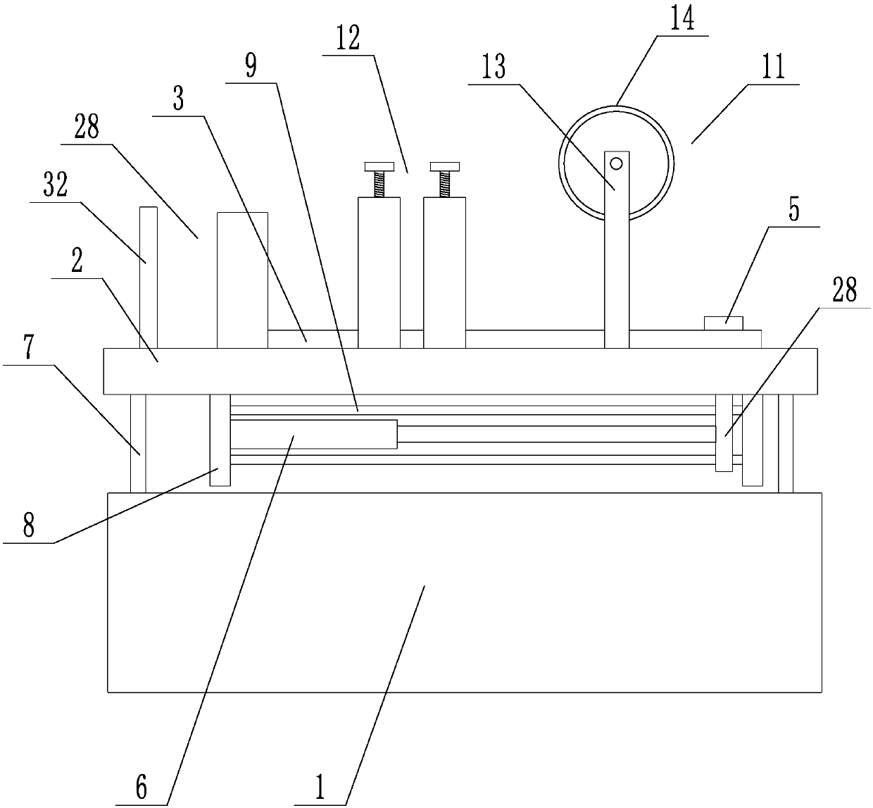
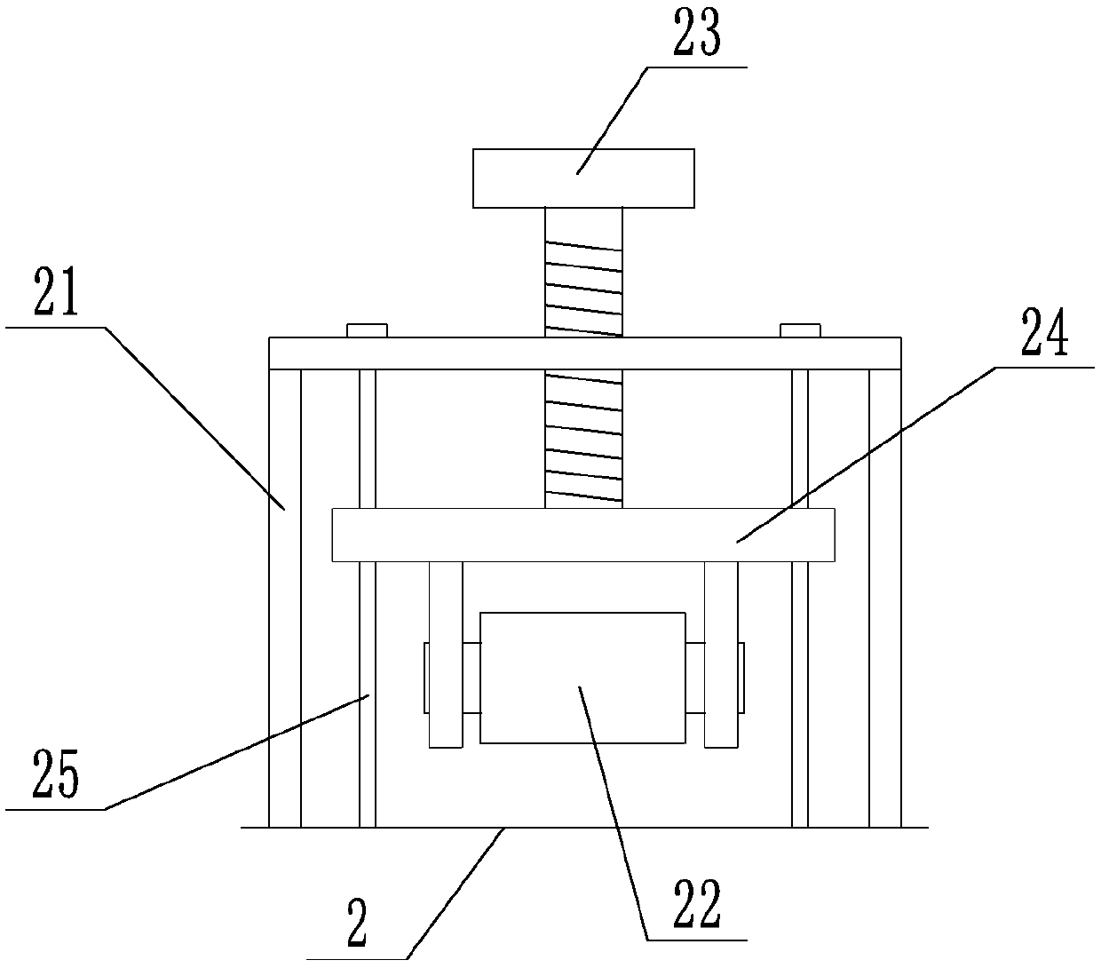
[0022] like Figure 1 to Figure 5 As shown, a nixie tube film sticking cutting equipment includes a base 1, a film sticking platform 2 is arranged on the base 1, and two parallel limit bars 3 are set in the middle of the film sticking platform 2 along its length direction, and the two limit bars 3 There is a limit groove 4 between them. A push block 5 is movable in the limit groove 4. The push block 5 is connected to the first cylinder 6 and driven by the first cylinder 6 to slide in the limit groove 4. Above the chute Along the conveying direction of the nixie tube, there are successively arranged a film feeding mechanism 11 for providing a film, a rolling mechanism 12 for flattening the film and covering it on the surface of the nixie tube, a cutting mechanism 28, and a film set at the end of the limit groove 4. Limiting plate 32, cutting mechanism 28 comprises the knife rest 29 that is arranged on the limit groove 4 tops and the blade 30 that is arranged on the knife rest 2...


PUM


Abstract

The invention discloses digital tube film pasting and cutting equipment which comprises a base. The base is provided with a film pasting platform, the middle of the film pasting platform is provided with two parallel limiting strips in the length direction, a limiting groove is formed between the two limiting strips, a push block is movably arranged in the limiting groove, the push block is connected with a first air cylinder and driven by the first air cylinder to slide in the limiting groove, a film supply mechanism, a rolling mechanism, a cutting mechanism and a limiting plate arranged at the end of the limiting groove are sequentially arranged above the sliding groove in the conveying direction of digital tubes, the cutting mechanism comprises a tool rest straddling the limiting grooveand a blade arranged on the tool rest, the tool rest is provided with a tool slot, the two sides of the blade are in sliding fit with the tool slot, and the blade is driven by a second air cylinder to move up and down along the tool slot. The digital tube film pasting and cutting equipment has the advantages that accurate cutting can be automatically achieved after film pasting, and digital tubefilm pasting efficiency is improved.

Description

technical field [0001] The invention relates to a film sticking device, in particular to a film sticking device for a digital tube. Background technique [0002] LED digital tubes (LED Segment Displays) are packaged together by multiple light-emitting diodes to form an "8"-shaped device. The leads have been connected internally, and it is only necessary to lead out their individual strokes and common electrodes. The digital tube is actually composed of seven light-emitting tubes in a figure-eight shape, and adding a decimal point is eight. These segments are represented by the letters a, b, c, d, e, f, g, dp, respectively. [0003] In the production process of digital tubes, the steps generally include: putting the pins on the circuit board, fixing the chip on the circuit board, baking, initial inspection, glue filling and general inspection. After the above steps are completed, the surface of the nixie tube will be pasted with a film. The traditional method of pasting the...

Claims


Application Information

Patent Timeline
Patent Type & Authority Applications(China)
IPC IPC(8): B26F1/40B26D7/00G09F9/33B65B33/02
CPCG09F9/33B65B33/02B26D7/00B26F1/40
Inventor 吴雪光
Owner JIANGMEN PENGJIANG AREA JINGHUI ELECTRONICS SCI & TECH CO LTD
Why Eureka
Try Eureka