Method for determining leakage in hydraulic brake system

A brake system and hydraulic technology, applied in the direction of brake safety systems, brakes, brake components, etc., can solve problems such as the inability to use caliper integrated motors

Active Publication Date: 2018-03-06
ROBERT BOSCH GMBH
View PDF10 Cites 0 Cited by
  • Summary
  • Abstract
  • Description
  • Claims
  • Application Information

AI Technical Summary

Problems solved by technology

Such an approach cannot be applied to today's Motor-on-Caliper (MoC) APBs because the design does not contain the same components
[0004] However, since for MoC parking brakes the piston is moved when the clamping force is built up and thus the volume is displaced, monitoring, such as for example leakage monitoring, can play a role during the actuation of the MoC parking brake.

Method used


Image

  • Method for determining leakage in hydraulic brake system
  • Method for determining leakage in hydraulic brake system
  • Method for determining leakage in hydraulic brake system

Examples


Embodiment Construction

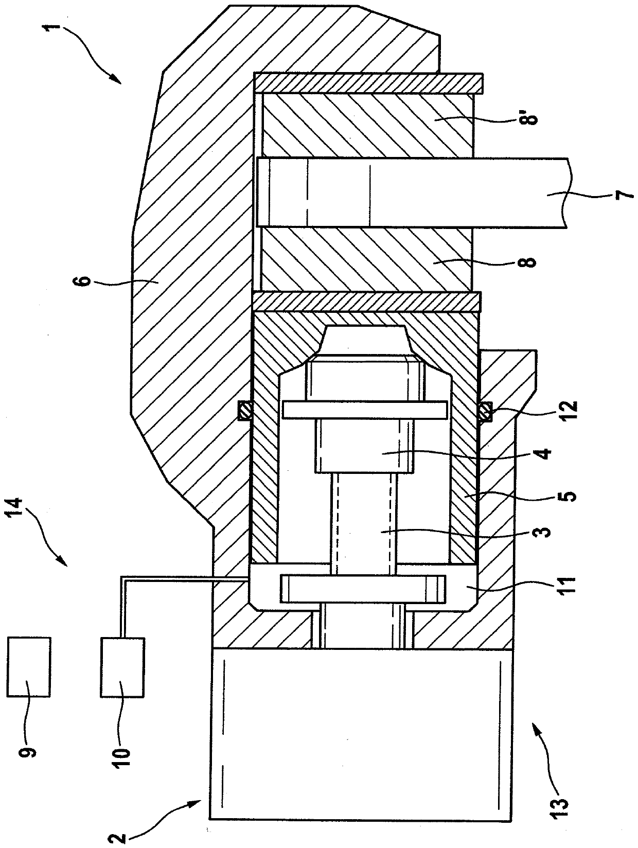
[0050] figure 1 A schematic sectional view of a braking device 1 for a vehicle is shown. The braking device 1 here has an automated parking brake 13 (also referred to as automatic parking brake or automated parking brake, APB for short), which can be activated by means of an electromechanical actuator. 2 (electric motor) to apply the clamping force used to hold the vehicle in place. For this purpose, the electromechanical actuator 2 of the parking brake 13 shown drives a spindle 3 , in particular a threaded spindle 3 , which is supported in the axial direction. On its end facing away from the actuator 2 , the spindle 3 is provided with a spindle nut 4 , which bears against the automated parking brake 13 in the pressed state. Piston 5 on. In this way, the parking brake 13 transmits force to the brake linings 8 , 8 ′ or the brake disk 7 . In this case, the spindle nut bears against the inner end face of the brake piston 5 (also referred to as the rear side of the brake pisto...


PUM


Abstract

A method for determining a leakage in a hydraulic brake system in a vehicle includes evaluating a suspected leakage in the hydraulic brake system and taking into account an actuation of an automated hand brake during the evaluation of the suspected leakage. The hydraulic brake system has a hydraulic footbrake and the automated hand brake has an electromechanical actuator. The hydraulic footbrake and the automated hand brake are configured to act on the same brake piston. In addition, a device, a computer program, and a storage medium are arranged.

Description

technical field [0001] The invention relates to a method for detecting leaks in a hydraulic brake system in a vehicle having a hydraulic service brake and an automated parking brake, the parking brake having an electromechanical actuator and the The service brake also acts on the same brake piston, wherein the method is characterized in that the actuation of the automated parking brake is taken into account in the evaluation of the leakage presumption. Furthermore, an apparatus, a computer program, and a storage medium are provided. Background technique [0002] So-called caliper-integrated motor parking brakes are known from the prior art, as disclosed, for example, from patent application DE 10 2011 004 772 A1. [0003] Furthermore, the patent application DE 10 2004 062 824 A1 is known from the prior art. This document relates to a method for checking a parking brake. The method is used to check the functional capability of the pressure build-up in the parking brake. C...

Claims


Application Information

Patent Timeline
Patent Type & Authority Applications(China)
IPC IPC(8): B60T17/22B60T13/74
CPCB60T13/745B60T17/22B60T8/4872B60T13/741B60T7/085B60T8/1881B60T17/221B60T17/225B60T17/226
Inventor H.沃尔夫D.布拉泰特E.曼赫茨
Owner ROBERT BOSCH GMBH
Why Eureka
Try Eureka