Turnouts using cam groove for track switching

A technology of cam grooves and rails, which is applied to mechanical equipment for manipulating turnouts or line breakers, electrical equipment for manipulating turnouts or line breakers, railway car body parts, etc., and can solve the problem of reducing life expectancy and screw wear , affect lane change and other issues, to achieve the effect of improving service life, ensuring safety of track change, and improving bearing capacity

Inactive Publication Date: 2018-03-06
柴薪
View PDF7 Cites 3 Cited by
  • Summary
  • Abstract
  • Description
  • Claims
  • Application Information

AI Technical Summary

Problems solved by technology

Most of the target turnout structures use screw rods to change lanes. For example, Chinese patent CN205917534U discloses a turnout based on urban rail transit. The track changing device adopts a servo motor, and the output shaft of the servo motor is connected with a screw rod. There is a movable plate connected with it, the top of the movable plate is connected with a connecting shaft, the servo motor works, and then the screw rod drives the movable plate to move left and right, so that the turnout track can be controlled to move left and right to realize lane change to the left or to the right. However, this The track change of the turnout with this structure is driven by a screw rod. Since the wheel will generate a large vibration force when the track is changed, the screw drive will easily cause the wear of the screw rod, which will reduce its life if it is light, and affect its lane change if it is serious. Therefore, it is necessary to improve its track changing device. At the same time, due to the great vibration of the current turnout, it is easy to make the position of the turnout unable to be accurately guaranteed due to long-term use, and the turnout is easily deformed due to the rigidity of the turnout under vibration. , affecting lane change

Method used


Image

  • Turnouts using cam groove for track switching
  • Turnouts using cam groove for track switching
  • Turnouts using cam groove for track switching

Examples


Embodiment Construction

[0018] The following will clearly and completely describe the technical solutions in the embodiments of the present invention with reference to the accompanying drawings in the embodiments of the present invention. Obviously, the described embodiments are only some, not all, embodiments of the present invention. Based on the embodiments of the present invention, all other embodiments obtained by persons of ordinary skill in the art without making creative efforts belong to the protection scope of the present invention.

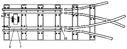
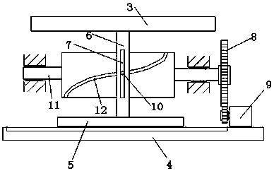
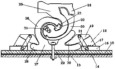
[0019] see Figure 1-4 , the present invention provides a technical solution: a track switch using cam grooves, which includes a track first assembly, a second track assembly, a turnout track assembly 2 and a track change assembly, wherein the track first assembly includes two symmetrically arranged Track one 1, the switch track assembly 2 is arranged in pairs between the two track one, the end of the switch track assembly 2 is provided with the track two of t...


PUM


Abstract

The invention discloses turnouts using a cam groove for track switching. A track-switching assembly is arranged between two turnout track assemblies; the track-switching assembly uses a cam mode of acam cylinder and the cam groove to drive the movement of a track-switching driving plate; the track-switching driving plate realizes the track switching by controlling the left-right movement of the turnout track assemblies; and the ends of the turnout track assemblies are mounted on track sleepers by slightly-rotational damping assemblies. The turnouts using the cam groove for the track switchinguse the cam groove to drive the track switching instead of screw rods in the prior art, and the cam groove has high wear resistance and can bear greater vibration force, so as to improve the bearingcapacity of the track switching, to enhance the service life and to ensure the safety of the track switching. The turnouts are arranged on the slightly-rotational damping assemblies and can slightly swing during the track switching process, so as to prevent the turnouts from being subjected to excessive rigidity force, to avoid fatigue problems of the turnouts and to greatly improve the service life of the turnouts and the adaptability of the track switching of the turnouts.

Description

technical field [0001] The invention relates to a track switch using a cam groove, which belongs to the technical field of transportation equipment. Background technique [0002] In rail transportation, a turnout is a line connection device that allows rolling stock to transfer from one track to another, and is also one of the weak links of the track. It is usually laid in large numbers at stations and marshalling yards. With the turnout, the passing capacity of the line can be fully utilized. Even if it is a single-track railway, the train can be separated by laying a turnout and building a section of fork that is greater than the length of the train. Turnouts play an important role on railway lines. Most of the target turnout structures use screw rods to change lanes. For example, Chinese patent CN205917534U discloses a turnout based on urban rail transit. The track changing device adopts a servo motor, and the output shaft of the servo motor is connected with a screw ro...

Claims


Application Information

Patent Timeline
Patent Type & Authority Applications(China)
IPC IPC(8): B61L5/02B61L5/06
CPCB61L5/02B61L5/065
Inventor 柴薪
Owner 柴薪
Why Eureka
Try Eureka