Three-axis aircraft and moving and taking off method

A technology for an axis aircraft and a multi-rotor aircraft, which is applied in aircraft, unmanned aircraft, landing gear, etc., can solve the problems of increased flight resistance, low efficiency, and large heat loss of the motor, and achieve the effect of sensitive lift and thrust

Pending Publication Date: 2018-03-06
ZHUHAI PANLEI INTELLIGENT TECH CO LTD
View PDF6 Cites 4 Cited by
  • Summary
  • Abstract
  • Description
  • Claims
  • Application Information

AI Technical Summary

Problems solved by technology

[0004] Existing multi-axis aircraft basically only adjust the flight attitude by changing the rotor speed. Translational flight needs to tilt the fuselage, thus increasing the windward area of ​​the fuselage, resulting in an increase in flight resistance, making the multi-axis aircraft slow in response and poor in maneuverability , the frequent acceleration and deceleration of the motor caus...

Method used


Image

  • Three-axis aircraft and moving and taking off method
  • Three-axis aircraft and moving and taking off method
  • Three-axis aircraft and moving and taking off method

Examples


Embodiment 2

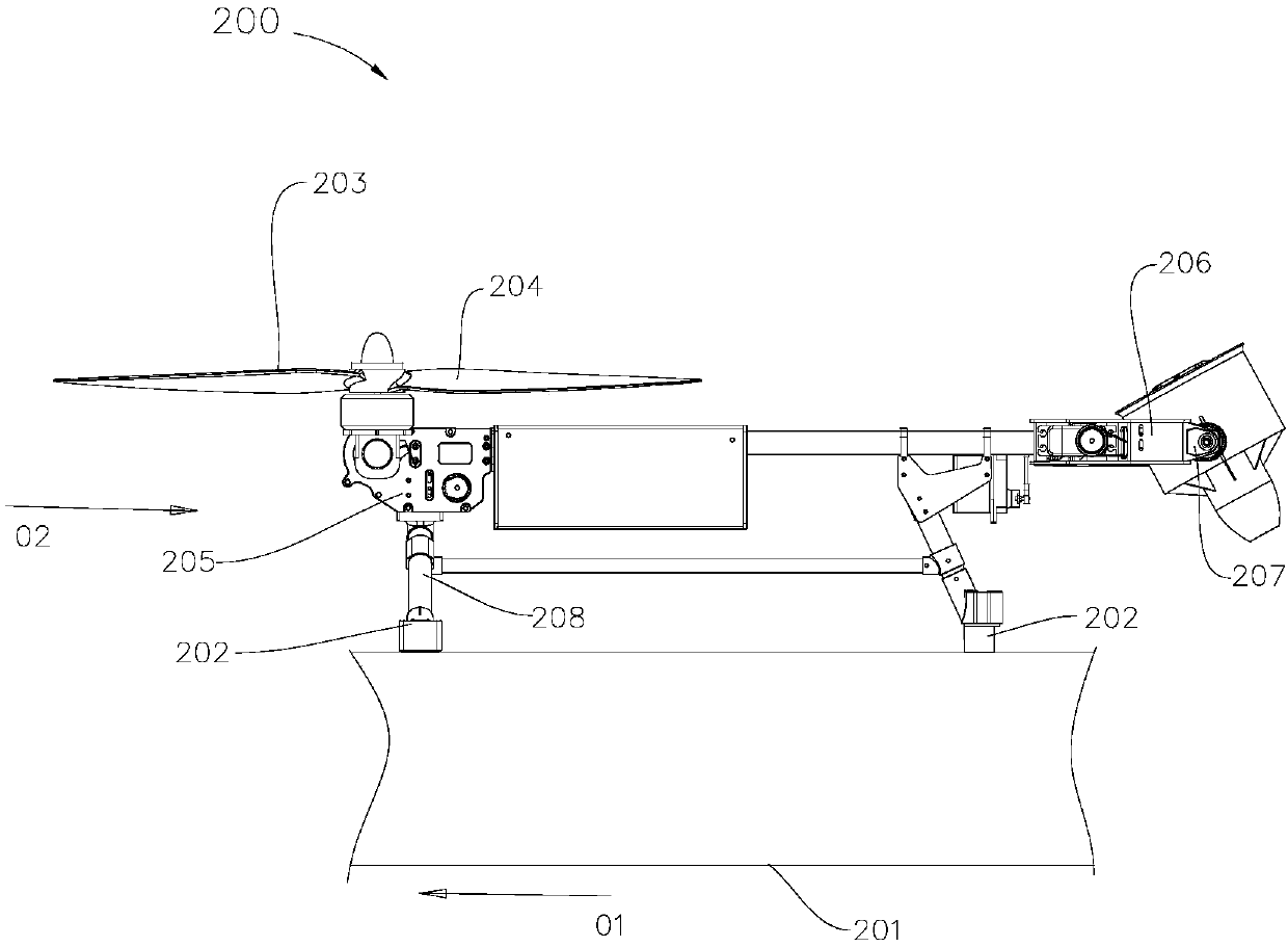
[0044] Such as Figure 4 As shown, the mobile take-off method of the quadrocopter includes the following steps:

[0045] S1. The three-axis aircraft 300 is fixed on the platform 301 moving along the direction 01 through the electromagnet 302 .

[0046] S2, the first tilting drive device 305 controls the first rotor 303 and the second rotor tilt 304, so that the lower ends of the respective rotation axes of the first rotor 303 and the second rotor 304 face the incoming flow 02; the second tilting drive 307 The third rotor 306 is controlled to tilt so that the lower end of the rotation axis of the third rotor 306 faces away from the incoming flow 02 .

[0047] S3. Increase the rotation speed of the rotor. After the rotation speed of the rotor, the generated thrust or the throttle reaches a predetermined value, the locking of the platform 301 by the electromagnet 302 is released.

[0048] The lower ends of the respective rotation axes of the first rotor 303 and the second rotor...


PUM


Abstract

The invention provides a three-axis aircraft with high maneuverability. The three-axis aircraft comprises a fuselage, rotors and a power device driving the rotors to rotate. The rotors include the first rotor, the second rotor and the third rotor. The first rotor and the second rotor are symmetrically mounted on the two sides of the fuselage and near the front end of the fuselage. The third rotoris mounted at the position near the back end of the fuselage. A deflection driving device is mounted on the fuselage to drive the third rotor to obliquely rotate around the axis of the length direction of the fuselage. The first rotor and the second rotor have the same diameter, and the diameters of the first rotor and the second rotor are greater than the diameter of the third rotor. The maneuverability of the three-axis aircraft is advantageously improved.

Description

technical field [0001] The invention relates to a multi-axis aircraft, in particular to a high-maneuverability three-axis aircraft and a mobile take-off method. Background technique [0002] A multicopter usually includes a fuselage, an arm, a flight control device, a power supply, an ESC, a drive device, a rotor and functional sensors. The drive unit that drives the rotor to rotate can be a motor, an oil engine or a power unit with a speed changer. The power plant of some aircraft is connected with the differential gear input shaft, and the two output shafts of the differential gear are respectively connected with a rotor. A power unit can be used to drive two rotors to rotate through a differential. [0003] The announcement number is CN105059558A, which discloses a take-off and landing system for unmanned ship-borne UAVs. for multicopters. In a suitable airflow environment, cancel the electromagnetic force between the unmanned ship and the UAV, and release the UAV. I...

Claims


Application Information

Patent Timeline
IPC IPC(8): B64C27/08B64C27/12B64C27/52B64C25/32
CPCB64C25/32B64C27/08B64C27/12B64C27/52B64U10/10
Inventor 何春旺
Owner ZHUHAI PANLEI INTELLIGENT TECH CO LTD
Why Eureka
Try Eureka