
A Fracturing Method for Low Permeability Heavy Oil Reservoir

A heavy oil reservoir, low permeability technology, applied in the direction of earthwork drilling, wellbore/well components, production fluid, etc., can solve the problems of low formation heating capacity, casing damage, difficult development, etc., and achieve improved stimulation effect , reduce cold damage, broad application prospects

Active Publication Date: 2020-05-08
PETROCHINA CO LTD
View PDF5 Cites 0 Cited by
  • Summary
  • Abstract
  • Description
  • Claims
  • Application Information

AI Technical Summary

Problems solved by technology

At present, the development of heavy oil reservoirs is mainly the heavy oil steam huff and puff technology, but this technology has the following problems: the cost of steam huff and puff is high, the heat loss during the steam injection process is large, and the casing may be damaged. At the same time, this technology is suitable for For large-scale development of reservoirs, it is difficult to benefit from the development of heavy oil reservoirs dominated by the following fault blocks
There are few reports on the fracturing of heavy oil reservoirs. Domestically, the self-generating heat technology of fracturing fluids has been proposed to reduce the viscosity of crude oil. However, considering the effective filtration depth of fracturing fluids in reservoirs, the heating capacity Smaller (Zheng Kexiang, Yi Baoan, Yuan Wenyi, etc. Self-generated heat and low-damage alkaline fracturing technology for heavy oil reservoirs, Journal of Petroleum and Natural Gas, 2010, 32(4): 298-301), limited improvement in stimulation effect

Method used


Image

  • A Fracturing Method for Low Permeability Heavy Oil Reservoir
  • A Fracturing Method for Low Permeability Heavy Oil Reservoir
  • A Fracturing Method for Low Permeability Heavy Oil Reservoir

Examples


Embodiment 1

[0036] This example provides a technical method for improving the fracturing effect of low-permeability heavy oil reservoirs. In this method, a well in Huabei Oilfield is selected as a test oil well. Rate 5-10 x 10 -3 μm2 , porosity 12-17%, formation pressure 17MPa, reservoir thickness 15m. The technical method of the present embodiment comprises the following steps:

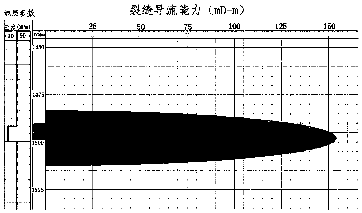
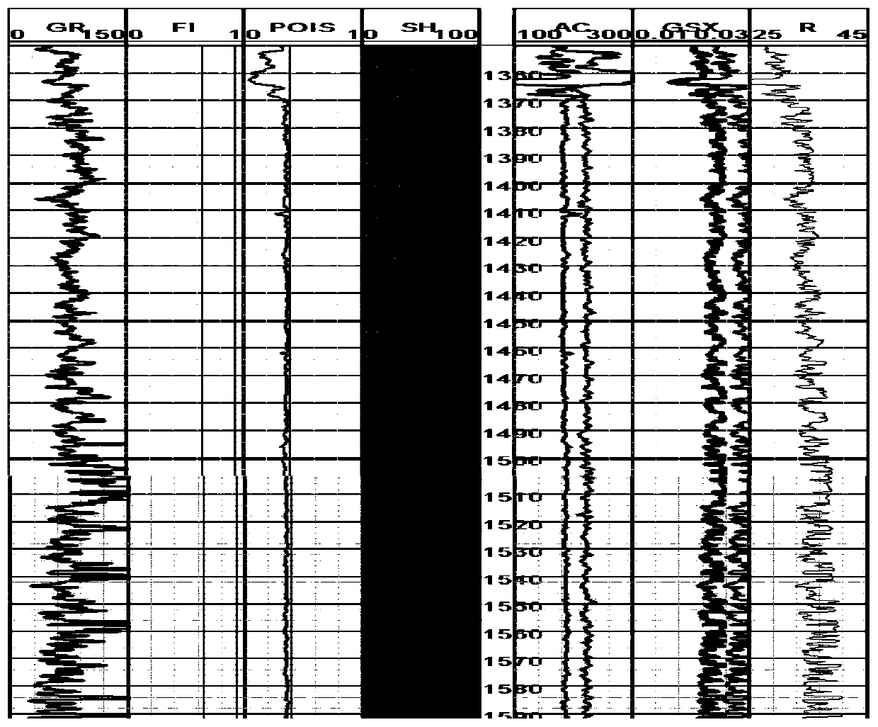
[0037] Step 1: According to the indoor triaxial mechanical experiment and logging data, the rock mechanical parameters of the reservoir are calculated as Young's modulus of 11200-19870MPa, Poisson's ratio of 0.17-0.22 (the indoor triaxial mechanical experiment and measured The method of calculating rock mechanical parameters from well data is a conventional method in this field), according to the designed pump injection program, the effective length of the propped fracture is 140m by using the FracPT fracturing design software simulation, as figure 1 shown.

[0038] According to the fracture simulation result...


PUM


Abstract

The invention provides a low-permeability thick-oil oil reservoir fracturing method. The low-permeability thick-oil oil reservoir fracturing method comprises the following steps that reservoir rock mechanical parameters and logging data are obtained, the fracturing crack parameters are obtained through simulation, and the needed viscosity-decreasing liquid preparation quantity is obtained throughcalculation; according to data of adjacent wells and the logging data, the stratum fracture pressure of a transformed layer section of a fracturing well is calculated, and the highest injection displacement Qmax of viscosity-decreasing liquid when a reservoir is not fractured open is calculated; the viscosity-decreasing liquid is prepared from hot water, the viscosity-decreasing liquid is injectedinto the reservoir at the injection displacement being 0.9 time the Qmax at the matrix injection stage, after the matrix injection stage is finished, the injection displacement is increased to fracture the reservoir open, and the remaining viscosity-decreasing liquid continues being injected into the reservoir to enable the impact range of the viscosity-decreasing liquid to be larger than that ofhydraulic cracks; and after injection of the viscosity-decreasing liquid is finished, well kill is conducted for 2-5 days, then fracturing liquid is prepared from warn water, fracturing transformingis conducted on a thick-oil well according to the end sand removal transforming mode, and after fracturing transforming is finished, the well is closed for 2 h to conduct rapid back flow.

Description

technical field [0001] The invention belongs to the technical field of production stimulation and transformation of oil and gas wells, and relates to a fracturing method for low-permeability heavy oil reservoirs. Background technique [0002] With the continuous deepening of exploration and development, the inferiority of my country's oil and gas resources has been intensified, and the goal of exploration and development has gradually expanded to "difficult and new" fields. As a realistic oil and gas resource, medium-shallow heavy oil reservoirs are widely distributed in the Zhungeer Basin, Songliao Basin, and Bohai Bay Basin in my country, and have become an important area for increasing reserves and production. At present, the development of heavy oil reservoirs is mainly the heavy oil steam huff and puff technology, but this technology has the following problems: the cost of steam huff and puff is high, the heat loss during the steam injection process is large, and the ca...

Claims


Application Information

Patent Timeline
Patent Type & Authority Patents(China)
IPC IPC(8): E21B43/26
CPCE21B43/26
Inventor 何春明才博蔡军吴刚段贵府穆海林姜伟
Owner PETROCHINA CO LTD
Learn More