Work method of detecting device of hydraulic cylinder for lathe

A technology for detection devices and working methods, which is applied in fluid pressure actuation devices, fluid pressure actuation system testing, mechanical equipment, etc., and can solve problems such as high cost and easy damage

Active Publication Date: 2018-03-06
宁波信基机械科技有限公司
View PDF3 Cites 1 Cited by
  • Summary
  • Abstract
  • Description
  • Claims
  • Application Information

AI Technical Summary

Problems solved by technology

However, when current manufacturers detect hydraulic cylinders, they often need a set of complex electronic induction monitoring equipment to detect various indicators of hydraulic cylinders. The cost is too high, and the electronic devices are relatively sophisticated. very fragile

Method used


Image

  • Work method of detecting device of hydraulic cylinder for lathe

Examples


Embodiment Construction

[0016] The present invention will be described in further detail below by means of specific embodiments:

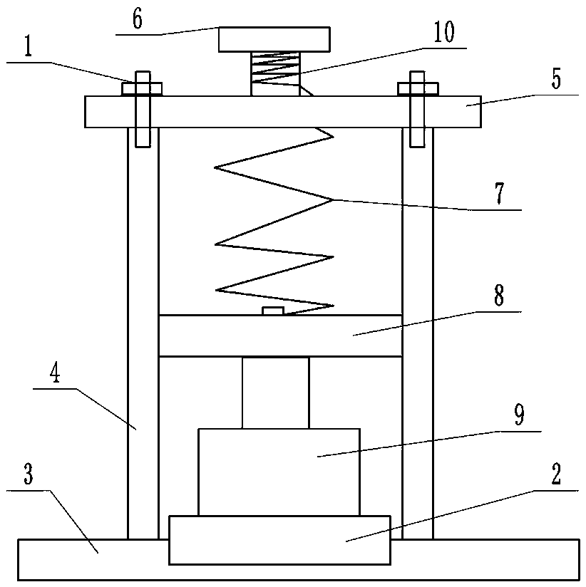
[0017] The reference signs in the drawings of the description include: bolt 1, groove 2, base 3, travel box 4, cover plate 5, rectangular block 6, spring 7, horizontal plate 8, hydraulic cylinder 9, screw rod 10.

[0018] The embodiment is basically as figure 1 Shown:

[0019] The hydraulic cylinder detection device for a lathe of this embodiment comprises a base 3, which is provided with a groove 2 for placing the hydraulic cylinder 9; the base 3 is provided with a stroke box 4, and the inner wall of the stroke box 4 is provided with a chute, and the slide A horizontal plate 8 is slidably connected to the groove, and the side wall of the stroke box 4 is provided with a scale. A hydraulic cylinder 9 to be detected is placed under the horizontal plate 8. The output end of the hydraulic cylinder 9 is offset against the bottom surface of the horizontal plate 8, and the top ...


PUM


Abstract

The invention belongs to the field of hydraulic devices and particularly relates to a work method of a detecting device of a hydraulic cylinder for a lathe. The detecting device of the hydraulic cylinder for the lathe comprises a base. A groove for holding the hydraulic cylinder is arranged in the base. A travel box is arranged on the base. A sliding groove is arranged on the inner wall of the travel box. A transverse plate is connected with the sliding groove in a sliding manner. Scales are arranged on the side wall of the travel box. The hydraulic cylinder to be detected is arranged below the transverse plate. The output end of the hydraulic cylinder abuts against the bottom face of the transverse plate. The top of the travel box is fixedly provided with a cover plate through bolts. Thecover plate is provided with a hole. A threaded rod is rotationally connected with the cover plate. A rectangular block used for rotating the threaded rod is fixedly connected with the top of the threaded rod. A spring is fixedly connected with the upper surface of the transverse plate. The end, far away from the transverse plate, of the spring penetrates through the hole of the cover plate to befixedly connected with the threaded rod. Water with the level of 3cm is contained by the transverse plate. Western red dye with the density smaller than that of water is mixed with the water. According to the work method of the detecting device of the hydraulic cylinder for the lathe, electronic devices high in cost are not needed, the structure is simple, observation is convenient, and the detecting device is a mechanical component and is not prone to damage.

Description

technical field [0001] The invention belongs to the field of hydraulic equipment, and in particular relates to a working method of a hydraulic cylinder detection device for a lathe. Background technique [0002] In the machinery industry, the hydraulic cylinder is an important part of power transmission. It is a device that converts hydraulic energy into mechanical energy and enables the machine to achieve reciprocating linear motion or swing. Its transmission works smoothly and has high reliability. The hydraulic cylinder is located The working environment is harsh, especially in the metallurgy, mining and shipping industries, which have high requirements for the operation of machinery and equipment. During the mechanical transmission process, the hydraulic cylinder is in a harsh working environment of high pressure, impact and instability. In the control of industrial production In the process, a large number of hydraulic cylinders are used. For example, when workpieces a...

Claims


Application Information

Patent Timeline
Patent Type & Authority Applications(China)
IPC IPC(8): F15B19/00
CPCF15B19/00
Inventor 王健
Owner 宁波信基机械科技有限公司
Why Eureka
Try Eureka