Supercharge Your Innovation With Domain-Expert AI Agents!

Conduction oil boiler feeding device

A technology of heat transfer oil boiler and feeding device, which is applied in supply configuration, fuel supply, solid fuel pretreatment, etc., can solve problems such as low efficiency, manual stirring, and waste of manpower and material resources, and achieve the effect of high efficiency and high efficiency.

Inactive Publication Date: 2018-03-06
安徽长城锅炉制造有限公司
View PDF4 Cites 0 Cited by
  • Summary
  • Abstract
  • Description
  • Claims
  • Application Information

AI Technical Summary

Problems solved by technology

[0002] Heat-conducting oil boilers refer to boilers heated by heat-conducting oil. Generally, coal, oil, and steam are used as fuels, and heat-conducting oil is used as a medium. The coal filling operation for the heat transfer oil boiler is carried out manually, and in order to burn the coal more fully, it is necessary to manually stir the coal in the furnace, which consumes a lot of manpower and material resources, and is inefficient

Method used


Image

  • Conduction oil boiler feeding device

Examples


Embodiment Construction

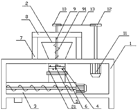
[0012] Such as figure 1 As shown, the present invention discloses a heat conduction oil boiler feeding device, comprising: a bracket 1, a feeding hopper 2, a screw conveyor 3, a rotating shaft 4, a bevel gear 5, a crushing cone 6, a column 7, a horizontal plate 8, a vertical Shaft 9, belt pulley one 10, motor 11, belt pulley two 12, belt 13, described feed hopper 2 is installed on support 1 top, and described screw conveyer 3 is installed on support 1 lower side, described feed hopper 2 The lower part is provided with a straight barrel portion 21, the straight barrel portion 21 of the feed hopper 2 is fixedly connected with the inlet of the screw conveyor 3, the rotating shaft 4 is installed in the straight barrel portion 21 through bearing rotation, and the bevel gear 5 is installed on the On the rotating shaft 4, the outer peripheral surface of the rotating shaft 4 is affixed with broken cones 6 distributed randomly, and a column 7 is vertically installed on the brackets 1 o...


PUM


Abstract

The invention discloses a conduction oil boiler feeding device. The conduction oil boiler feeding device comprises a bracket, a feeding hopper, a spiral conveyor, a rotary shaft, a bevel gear, crushing cones, vertical columns, a transverse plate, a vertical shaft, a first belt pulley, a motor, a second belt pulley and a belt. The lower portion of the feeding hopper is provided with a straight barrel part which is fixedly connected with an inlet of the spiral conveyor. The rotary shaft is rotationally installed in the straight barrel part through a bearing. The bevel gear is installed on the rotary shaft. The crushing cones distributed in disorder are fixedly connected to the peripheral face of the rotary shaft. The vertical shaft is rotationally installed in the middle of the transverse plate through a bearing. The first belt pulley is fixedly connected to the upper end of the vertical shaft. The lower end of the vertical shaft stretches into the feeding hopper, and the tail end of thevertical shaft is fixedly connected with a gear body engaged with the bevel gear. The motor is installed on the right side of the bracket. The second belt pulley is fixedly connected to the tail endof an output shaft of the motor. The first belt pulley and the second belt pulley are connected through the belt. The conduction oil boiler feeding device has the advantages of being novel in structure and high in efficiency.

Description

technical field [0001] The invention relates to a heat-conducting oil boiler feeding device, which is applied in the technical field of boiler transformation. Background technique [0002] Heat-conducting oil boilers refer to boilers heated by heat-conducting oil. Generally, coal, oil, and steam are used as fuels, and heat-conducting oil is used as a medium. The coal filling operation for the heat transfer oil boiler is carried out manually, and in order to burn the coal more fully, it is necessary to manually stir the coal in the furnace, which consumes a lot of manpower and material resources, and is inefficient. Contents of the invention [0003] In order to solve the defects of the prior art solutions, the invention discloses a heat conduction oil boiler feeding device, which has the advantages of saving time, effort and high efficiency. [0004] The invention discloses a heat conduction oil boiler feeding device, comprising: a bracket, a feeding hopper, a screw conve...

Claims


Application Information

Patent Timeline
IPC IPC(8): F23K1/00F23K3/00
CPCF23K1/00F23K3/00F23K2201/1006F23K2203/202
Inventor 王韦玲
Owner 安徽长城锅炉制造有限公司
Features
  • R&D
  • Intellectual Property
  • Life Sciences
  • Materials
  • Tech Scout
  • Unparalleled Data Quality
  • Higher Quality Content
  • 60% Fewer Hallucinations
Learn More