Vortex heater

A heater and vortex technology, which is applied in the field of vortex heaters, achieves the effects of low manufacturing cost, increasing heat exchange area and preventing ice blockage

Pending Publication Date: 2018-03-06
LESHAN CHUANTIAN GAS EQUIP
View PDF1 Cites 2 Cited by
  • Summary
  • Abstract
  • Description
  • Claims
  • Application Information

AI Technical Summary

Problems solved by technology

[0005] In order to overcome the defects and deficiencies in the above-mentioned prior art, the present invention provides a vortex heater, which is mainly used for heating the air intake of the pilot of the pressure regulator, to prevent the pilot from being blocked by ice, and to prevent the pressure regulator from shutting down. The purpose of the invention is to solve the heating problem of the gas pressure regulating skid in the prior art, and a heater is provided. The heater uses the heat generated by the high-pressure gas imported from the gas pipe network to heat, and the installation is simple and the energy consumption is low. Small, no need for external heating source, heater is simple to manufacture, low manufacturing cost

Method used


Image

  • Vortex heater
  • Vortex heater
  • Vortex heater

Examples


Embodiment 1

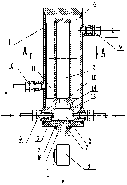
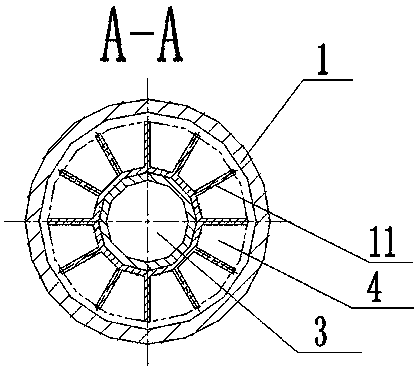
[0029] As a preferred embodiment of the present invention, with reference to the attached Figure 1-4 , this example discloses:

[0030] The vortex heater includes a heater body 1. The heater body 1 is provided with an air inlet chamber 2, a heating chamber 3 and a heat exchange chamber 4. The air inlet chamber 2 communicates with the heating chamber 3, and the air inlet chamber 2 An air inlet 5 is arranged on the air inlet 5, and a nozzle 6 is arranged at the air inlet 5, and the nozzle 6 injects the gas entered by the air inlet 5 into the air inlet chamber 2 along the tangential direction of the inner wall of the air inlet chamber 2, and the air inlet chamber 2. The diameter of one end of the upper air inlet 5 is greater than the diameter of the end of the air inlet chamber 2 communicating with the heating chamber 3. The air inlet chamber 2 is also provided with an exhaust port 7 for exhausting. The exhaust port 7 is externally connected to the There is an exhaust ball valv...

Embodiment 2

[0033] As another preferred embodiment of the present invention, with reference to the attached Figure 1-4 , this example discloses:

[0034] The vortex heater includes a heater body 1. The heater body 1 is provided with an air inlet chamber 2, a heating chamber 3 and a heat exchange chamber 4. The air inlet chamber 2 communicates with the heating chamber 3, and the air inlet chamber 2 An air inlet 5 is arranged on the air inlet 5, and a nozzle 6 is arranged at the air inlet 5, and the nozzle 6 injects the gas entered by the air inlet 5 into the air inlet chamber 2 along the tangential direction of the inner wall of the air inlet chamber 2, and the air inlet chamber 2. The diameter of one end of the upper air inlet 5 is greater than the diameter of the end of the air inlet chamber 2 communicating with the heating chamber 3. The air inlet chamber 2 is also provided with an exhaust port 7 for exhausting. The exhaust port 7 is externally connected to the There is an exhaust bal...

Embodiment 3

[0038] As another preferred embodiment of the present invention, with reference to the attached Figure 1-4 , this example discloses:

[0039] The vortex heater includes a heater body 1. The heater body 1 is provided with an air inlet chamber 2, a heating chamber 3 and a heat exchange chamber 4. The air inlet chamber 2 communicates with the heating chamber 3, and the air inlet chamber 2 An air inlet 5 is arranged on the air inlet 5, and a nozzle 6 is arranged at the air inlet 5, and the nozzle 6 injects the gas entered by the air inlet 5 into the air inlet chamber 2 along the tangential direction of the inner wall of the air inlet chamber 2, and the air inlet chamber 2. The diameter of one end of the upper air inlet 5 is greater than the diameter of the end of the air inlet chamber 2 communicating with the heating chamber 3. The air inlet chamber 2 is also provided with an exhaust port 7 for exhausting. The exhaust port 7 is externally connected to the There is an exhaust bal...


PUM


Abstract

The invention discloses a vortex heater and relates to the technical field of natural gas pipeline networks. The present invention comprises a heater body, an air inlet chamber, a heating chamber and a heat exchange chamber are arranged on the heater body, the air inlet chamber communicates with the heating chamber, an air inlet is arranged on the air inlet chamber, and an air inlet is arranged at the air inlet A nozzle is provided, and the nozzle injects the gas entering from the air inlet into the air inlet chamber along the tangential direction of the inner wall of the air inlet chamber, the heat exchange chamber is formed between the shell of the heater body and the heating chamber, and the heater body A heat exchange air inlet and a heat exchange air outlet are arranged on the shell, and heat exchange fins are arranged on the outer wall of the heating chamber. The invention utilizes the heat generated by the high-pressure gas at the inlet of the gas pipe network for heating, has simple installation, low energy consumption, no external heating source, simple manufacture of the heater, and low manufacturing cost.

Description

technical field [0001] The invention relates to the technical field of natural gas pipeline network, in particular to a vortex heater. Background technique [0002] In the gas pressure regulating skid, because the pressure difference between the front and rear of the gas is too large or the ambient temperature is too low, the gas temperature will be too low, and the gas contains moisture, which will cause ice blockage in the gas pipeline and affect the gas supply, so a heater is required. Increase gas temperature. The heaters on the market include: electric heaters, water bath heaters, etc., all of which require an external heating source. The principle of this type of heater is: after the medium to be heated enters the heater, it flows in the annular space with the electric heating source for a certain period of time. Then flow out to achieve the purpose of raising the temperature. [0003] On June 18, 2014, the State Intellectual Property Office disclosed a utility model...

Claims


Application Information

Patent Timeline
Patent Type & Authority Applications(China)
IPC IPC(8): F24V40/00
Inventor 袁勇何文清王伟毛郑兰建强卢新友
Owner LESHAN CHUANTIAN GAS EQUIP
Why Eureka
Try Eureka