Drying device for chemical fiber cloth production

A drying device and cloth technology, which is applied in the direction of drying gas arrangement, drying solid materials, non-progressive dryer, etc., can solve the problems of slow natural drying speed of cloth, inconvenient movement of the bottom plate, low work efficiency, etc., to improve natural drying. Speed, ease of movement, improved support effect

Inactive Publication Date: 2018-03-06
JIANGSU KANGJIE MACHINERY
View PDF0 Cites 4 Cited by
  • Summary
  • Abstract
  • Description
  • Claims
  • Application Information

AI Technical Summary

Problems solved by technology

[0002] As we all know, the drying device for chemical fiber cloth production is an auxiliary device used in the production process of chemical fiber cloth to dry chemical fiber cloth so that it can be better produced. It has been widely used in the field of chemical fiber cloth production ; Existing chemical fiber cloth production drying device comprises top plate, base plate, left side plate, right side plate and four groups of supports, and the top of left side plate and right side plate is respectively installed on the left side and the right side of the top plate bottom, and the left side The bottom ends of the board and the right side board are installed on the top of the base plate, and the tops of the four sets of brackets are respectively installed on the left front side, right front side, left rear side and right rear side of the bottom end of the base plate, including two sets ...

Method used


Image

  • Drying device for chemical fiber cloth production
  • Drying device for chemical fiber cloth production
  • Drying device for chemical fiber cloth production

Examples


Embodiment Construction

[0014] The specific embodiments of the present invention will be described in further detail below in conjunction with the drawings and embodiments. The following examples are used to illustrate the present invention, but not to limit the scope of the present invention.

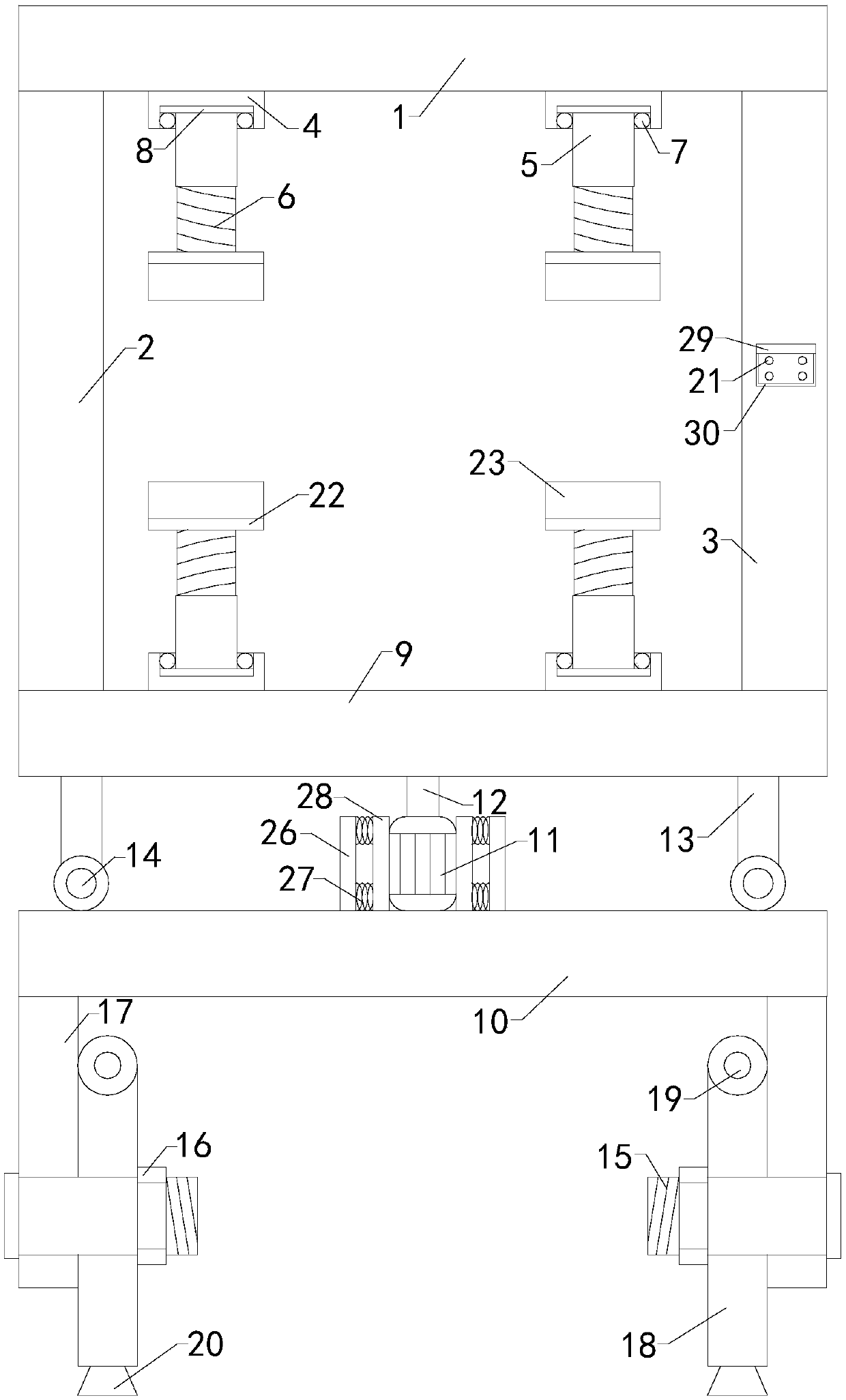
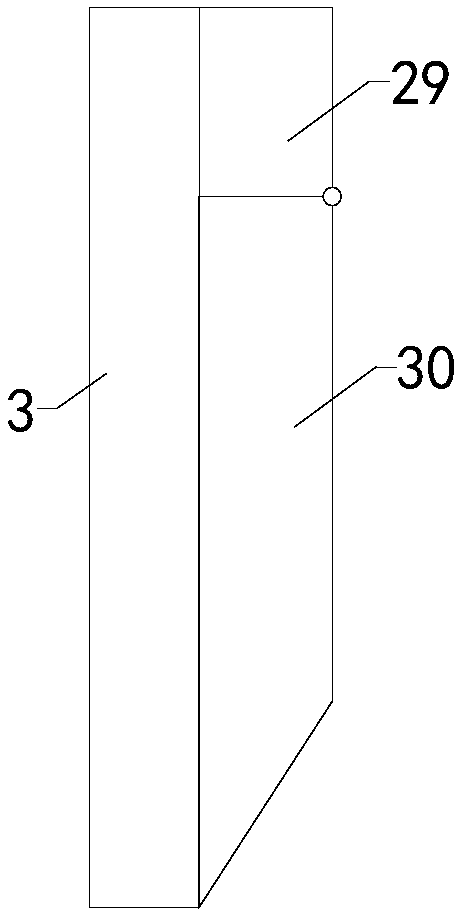
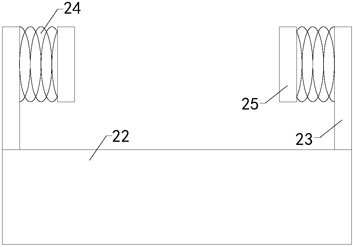
[0015] Such as Figure 1 to Figure 3 As shown, a drying device for the production of chemical fiber cloth of the present invention includes a top plate 1, a bottom plate, a left side plate 2, a right side plate 3 and four sets of brackets. The top ends of the left side plate and the right side plate are respectively installed at the bottom end of the top plate The left and right sides, the bottom ends of the left and right plates are all installed on the top of the bottom plate, and also includes two sets of upper fixing devices and two sets of lower fixing devices; both sets of upper fixing devices include upper slider 4 and upper thread Tube 5, upper threaded rod 6 and upper fixing clamp. The bottom ends of t...


PUM


Abstract

The invention relates to the technical field of chemical fiber cloth drying accessory devices, in particular to a drying device for chemical fiber cloth production. According to the drying device, twoupper fixing devices and two lower fixing devices can be conveniently adjusted according to the size of chemical fiber cloth, so that adaptability is improved; the natural drying speed of the cloth is increased, and working efficiency is improved; and a bottom plate can conveniently move, so that practicability is improved. The drying device comprises a top plate, the bottom plate, a left side plate, a right side plate and four supports; the two upper fixing devices each comprise an upper sliding block, an upper threaded pipe, an upper threaded rod and an upper fixing clamp; the two lower fixing devices each comprise a lower sliding block, a lower threaded pipe, a lower threaded rod and a lower fixing clamp; the bottom plate comprises an upper plate body and a lower plate body, and further comprises a motor, a transmission shaft, two supporting columns and two pulleys; the four supports each comprise a bolt, nuts, a supporting leg and a rotating column, wherein rollers are arranged atone ends of the four rotating columns, and suckers are arranged at the other ends of the four rotating columns.

Description

Technical field [0001] The present invention relates to the technical field of auxiliary equipment for drying chemical fiber cloth, in particular to a drying device for the production of chemical fiber cloth. Background technique [0002] As we all know, the drying device for the production of chemical fiber cloth is an auxiliary device used in the production process of chemical fiber cloth to dry the chemical fiber cloth so that it can better produce it. It is widely used in the field of chemical fiber cloth production. ; The existing drying device for chemical fiber cloth production includes a top plate, a bottom plate, a left side plate, a right side plate and four sets of brackets. The top ends of the left and right side plates are respectively installed on the left and right sides of the bottom of the top plate, and the left side The bottom ends of the plate and the right side plate are installed on the top of the bottom plate, and the top ends of the four sets of brackets a...

Claims


Application Information

Patent Timeline
IPC IPC(8): F26B11/00F26B21/00F26B25/02
CPCF26B11/00F26B21/00F26B25/02
Inventor 吴文杰吴进刘树森
Owner JIANGSU KANGJIE MACHINERY
Why Eureka
Try Eureka