Ultrasonic device

A technology of ultrasonic waves and steps, applied in radio wave measurement systems, instruments, etc., can solve problems such as complex structure and poor anti-environmental interference ability, and achieve the effect of improving accuracy and anti-environmental interference ability

Pending Publication Date: 2018-03-06
上海白泉声学科技有限公司
View PDF9 Cites 0 Cited by
  • Summary
  • Abstract
  • Description
  • Claims
  • Application Information

AI Technical Summary

Problems solved by technology

Therefore, when the ultrasonic device is installed on a drone (the drone just represents a machine with a complex structure and high detection distance accuracy), the existing ultrasonic device has the problem of poor anti-environmental interference

Method used


Image

  • Ultrasonic device
  • Ultrasonic device
  • Ultrasonic device

Examples


Embodiment 1

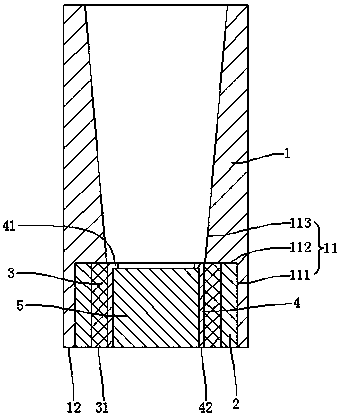
[0030] refer to figure 2 , an ultrasonic device, including a horn 1, a sealing ring 2, a flexible ring 3, a fixed ring 4 and a vibrating assembly 5, the vibrating assembly 5 includes several piezoelectric wafers, the vibrating assembly 5 is arranged in the sealing ring 2, and the fixed ring 4 is sleeved on On the vibrating assembly 5, the flexible ring 3 is clamped between the fixed ring 4 and the sealing ring 2, and the horn 1 is provided with a stepped hole 11, and the stepped hole 11 includes an upper stepped portion 111, a lower stepped portion 113 and a 111 and the connecting portion 112 of the lower stepped portion 113, the sealing ring 2 is inserted into the stepped hole 11, the sealing ring 2 is against the upper stepped portion 111 and the connecting portion 112, the connecting portion 112 and the vibrating assembly 5 are misplaced, along the stepped hole 11 In the axial direction, the lower step portion 113 includes at least two radial sections with different areas....

Embodiment 2

[0041] An ultrasonic device, including a horn, a sealing ring, a flexible ring, a fixed ring and a vibrating assembly, the vibrating assembly includes several piezoelectric wafers, the vibrating assembly is arranged in the sealing ring, the fixed ring is placed on the vibrating assembly, and the flexible ring is clamped on the fixed Between the ring and the sealing ring, there is a stepped hole on the horn. The stepped hole includes an upper stepped portion, a lower stepped portion and a connecting portion for connecting the upper stepped portion and the lower stepped portion. The sealing ring is inserted into the stepped hole. The sealing ring and The upper stepped part is in contact with the connecting part, and the connecting part and the vibrating assembly are dislocated. Along the axial direction of the stepped hole, the lower stepped part includes at least two radial sections with different areas.

[0042] In order to realize that the lower stepped portion includes at lea...

Embodiment 3

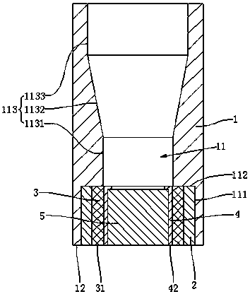
[0044] refer to image 3 , an ultrasonic device, including a horn 1, a sealing ring 2, a flexible ring 3, a fixed ring 4 and a vibrating assembly 5, the vibrating assembly 5 includes several piezoelectric wafers, the vibrating assembly 5 is arranged in the sealing ring 2, and the fixed ring 4 is sleeved on On the vibrating assembly 5, the flexible ring 3 is clamped between the fixed ring 4 and the sealing ring 2, and the horn 1 is provided with a stepped hole 11, and the stepped hole 11 includes an upper stepped portion 111, a lower stepped portion 113 and a 111 and the connecting portion 112 of the lower stepped portion 113, the sealing ring 2 is inserted into the stepped hole 11, the sealing ring 2 is against the upper stepped portion 111 and the connecting portion 112, the connecting portion 112 and the vibrating assembly 5 are misplaced, along the stepped hole 11 In the axial direction, the lower step portion 113 includes at least two radial sections with different areas. ...


PUM


Abstract

The present invention relates to an ultrasonic device. The problem is solved that an ultrasonic device is poor in anti-environment disturbance ability. The ultrasonic device comprises a horn, a sealing ring, a flexible ring, a fixing ring and a vibration module. The vibration module comprises a plurality of piezoelectric crystal plates; the vibration module is arranged in the sealing ring; the vibration module is sleeved with the fixing ring; the flexible ring is clamped between the fixing ring and the sealing ring; the horn is provided with a step hole; the step hole comprises an upper step portion, a lower step portion and a connection portion configured to connect the upper step portion with the lower step portion; the sealing ring is inserted into the step hole, and the sealing ring isabutted against the upper step portion and the connection portion; the connection portion is arranged with the vibration module in a staggered mode; and the lower step portion comprises at least tworadial sections with different areas along the axial direction of the step hole.

Description

technical field [0001] The invention relates to an ultrasonic device. Background technique [0002] refer to figure 1 , the transmitter on the ultrasonic device (since the structure of the transmitter and receiver is similar, therefore, figure 1 The structure shown can also be a receiver on an ultrasonic device) including a housing 01, a piezoelectric wafer 02, and a lead terminal 03. The housing 01 is provided with an accommodating cavity 011 and an avoidance hole 012 communicating with the accommodating cavity 011. The piezoelectric wafer 02 is installed in the accommodating cavity 011, and the lead terminal 03 is connected to the piezoelectric wafer 03. After the lead terminal 03 is energized, the piezoelectric wafer 02 generates a pulse signal. When the piezoelectric wafer 02 generates a pulse signal equal to the natural frequency of the piezoelectric wafer 02 , the piezoelectric chip 02 will vibrate and send out a sound wave signal to the outside through the avoidance...

Claims


Application Information

Patent Timeline
Patent Type & Authority Applications(China)
IPC IPC(8): G01S7/524
CPCG01S7/524
Inventor 葛虎于娟
Owner 上海白泉声学科技有限公司
Why Eureka
Try Eureka