Supercharge Your Innovation With Domain-Expert AI Agents!

Illumination panel and illumination device

A panel and integrated technology, applied in the field of lighting, can solve the problems of reducing integration and increasing assembly processes, so as to achieve the effect of improving integration and avoiding cumbersome procedures

Pending Publication Date: 2018-03-06
BOE TECH GRP CO LTD
View PDF0 Cites 0 Cited by
  • Summary
  • Abstract
  • Description
  • Claims
  • Application Information

AI Technical Summary

Problems solved by technology

[0004] However, the above-mentioned decorative film 11 and the lighting panel 10 are two independent components that are completed through different manufacturing processes. Therefore, in the manufacturing process of the planar lighting device, it is necessary to increase the assembly process to install the decorative film 11 to the light output of the lighting panel 10. side, reducing the integration of the product

Method used


Image

  • Illumination panel and illumination device
  • Illumination panel and illumination device
  • Illumination panel and illumination device

Examples


Embodiment Construction

[0038] The following will clearly and completely describe the technical solutions in the embodiments of the present invention with reference to the accompanying drawings in the embodiments of the present invention. Obviously, the described embodiments are only some, not all, embodiments of the present invention. Based on the embodiments of the present invention, all other embodiments obtained by persons of ordinary skill in the art without making creative efforts belong to the protection scope of the present invention.

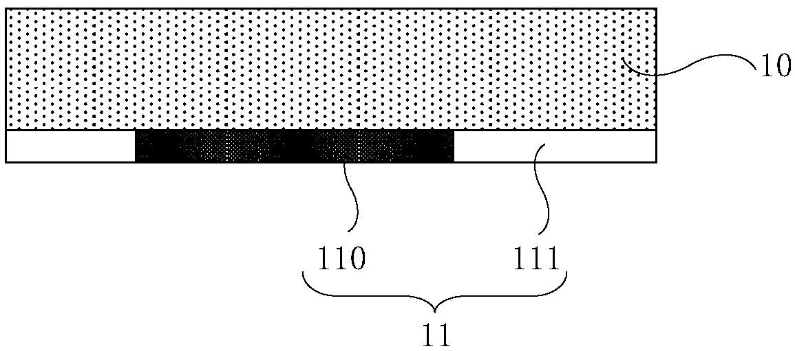
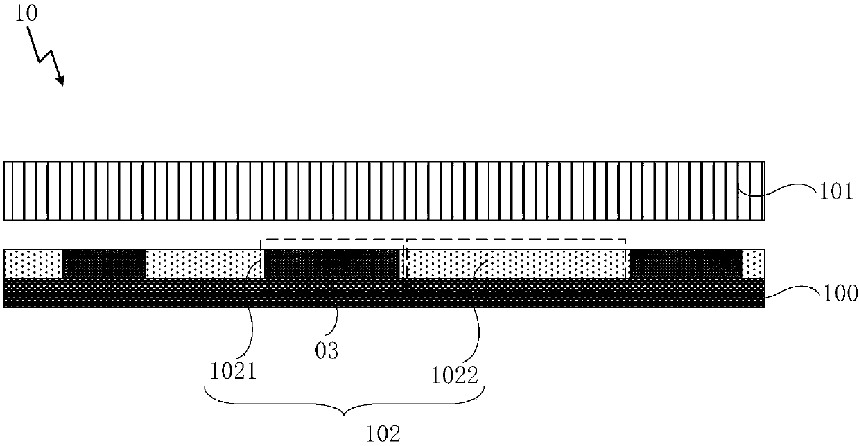
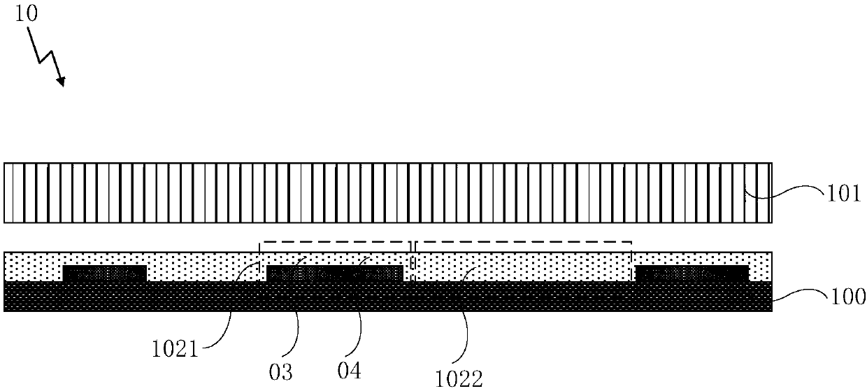
[0039] Examples of the present invention figure 2 As shown, a lighting panel 10 is provided. The lighting panel 10 includes a base substrate 100 and a light source layer 101 disposed on the base substrate 100 .

[0040] Wherein, an additional layer 102 is disposed between the base substrate 100 and the light source layer 101 , and the additional layer 102 includes a light-shielding portion 1021 and a light-transmitting portion 1022 .

[0041] Based on this,...


PUM


Abstract

The invention provides an illumination panel and an illumination device, and relates to the technical field of illumination. On the basis that ray cast is achieved, a tedious process brought by usageof a decorative film is avoided. The illumination panel comprises a substrate and a light source layer arranged on the substrate. An additional layer is arranged between the substrate and the light source layer, and comprises a shading portion and a transmitting portion. The illumination panel and the illumination device are used for illumination.

Description

technical field [0001] The invention relates to the technical field of illumination, in particular to an illumination panel and an illumination device. Background technique [0002] Organic Light Emitting Diode (OLED), as a current-mode light-emitting device, is increasingly being used because of its characteristics such as self-luminescence, fast response, wide viewing angle and the ability to be fabricated on flexible substrates. In flat lighting devices. [0003] In the prior art, in order to make the planar lighting device achieve a certain decorative effect, such as figure 1 As shown, a decorative film 11 with a light-transmitting area 110 and a light-shielding area 111 is usually provided on the light-emitting side of the lighting panel 10 in a planar lighting device. By setting the shapes and positions of the light-transmitting area 110 and the light-shielding area 111, a certain The decorative pattern, so that the light emitted by the lighting panel 10 can match th...

Claims


Application Information

Patent Timeline
Patent Type & Authority Applications(China)
IPC IPC(8): H01L27/32H10K99/00
CPCH10K59/88H10K59/00H10K59/12H10K59/131Y02E10/549Y02P70/50H10K59/221H10K59/179H10K59/126H10K50/86H10K50/865H10K59/805H01L27/156H01L33/42H01L33/58H01L33/62H10K59/10H10K50/805H10K59/84H10K77/111H10K2102/103H10K2102/311
Inventor 钟杰兴
Owner BOE TECH GRP CO LTD
Features
  • R&D
  • Intellectual Property
  • Life Sciences
  • Materials
  • Tech Scout
  • Unparalleled Data Quality
  • Higher Quality Content
  • 60% Fewer Hallucinations
Learn More