
Interference alignment method and system

A technology of interference alignment and interference matrix, which is applied in transmission systems, baseband systems, digital transmission systems, etc., can solve the problems of large amount of feedback, weak practicability, and inability to effectively utilize interference alignment, so as to improve system performance, be easy to implement, The effect of reducing the amount of feedback information

Inactive Publication Date: 2018-03-06
POTEVIO INFORMATION TECH
View PDF5 Cites 1 Cited by
  • Summary
  • Abstract
  • Description
  • Claims
  • Application Information

AI Technical Summary

Problems solved by technology

However, the channel error estimated by the analog feedback method is inversely proportional to the feedback SNR at high SNR, and the feedback power is generally limited. When the user feedback power is 120dB, the channel estimation error is generally 10 -7 order of magnitude, but the value in the channel matrix of the fading channel is generally also 10 -6 order of magnitude, resulting in a large relative error in channel estimation, and because of the small value, it is more sensitive to noise
Since the analog feedback is full feedback, the amount of feedback is huge, so its practicability is very weak
[0006] It can be seen that the existing interference alignment method has the problem that it cannot effectively take advantage of the interference alignment and is not conducive to practical applications.

Method used


Image

  • Interference alignment method and system
  • Interference alignment method and system
  • Interference alignment method and system

Examples


Embodiment Construction

[0020] In order to make the purpose, technical solution and advantages of the present invention clearer, the present invention will be further described in detail below in conjunction with the accompanying drawings and specific embodiments.

[0021] In order to facilitate the clear elaboration of the embodiments of the present invention, the principles on which the present invention is based are described as follows:

[0022] First build the system model as follows:

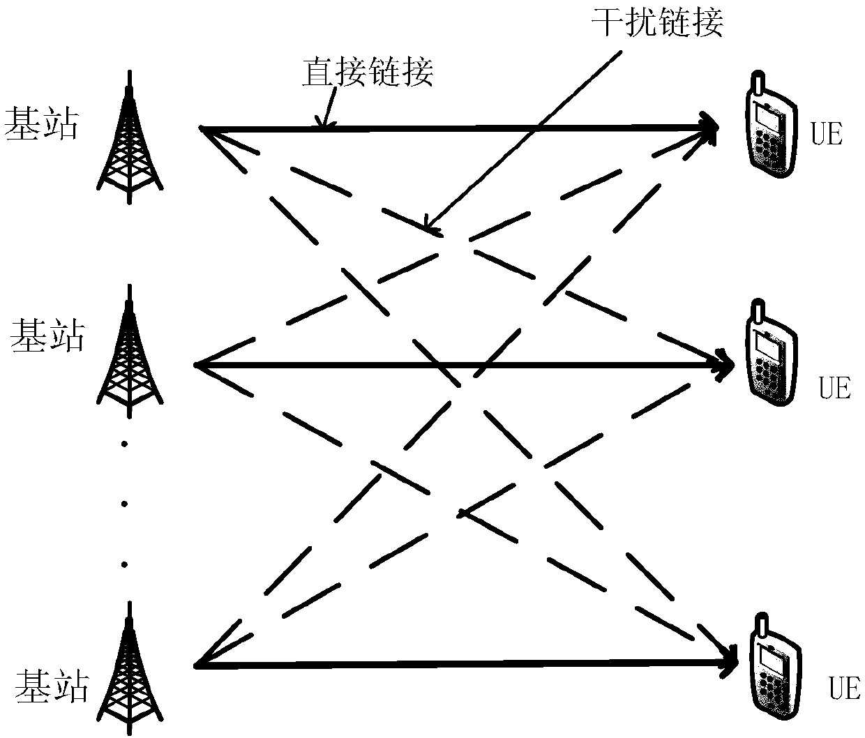
[0023] Under a K user to MIMO downlink interference channel, each base station N t antennas, each client N r Antennas. downlink channel matrix d is the number of data streams transmitted by each base station-user pair. Therefore, user j's received signal y j ∈ C d×1 can be written as:

[0024]

[0025] in is the transmission precoding matrix of the i-th base station, is the receiving decorrelation matrix of user j, z j Represents independent and identically distributed zero-mean Gaussian noise.

...


PUM


Abstract

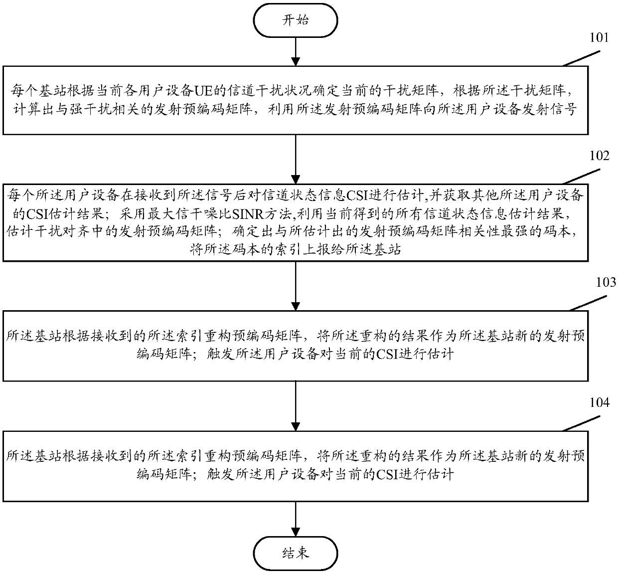
The invention discloses an interference alignment method and system. The interference alignment method comprises that each base station determines an interference matrix according to the channel interference condition of each user equipment (UE) at present, and works out an emission precoding matrix correlated to strong interference according to the interference matrix, and emits a signal to the UE by means of the emission precoding matrix; after receiving the signal, each UE estimates a CSI and obtains a CSI estimation result of another UE; an emission precoding matrix in interference alignment is estimated by means of all channel state information estimation results obtained at present through a maximum SINR method; a codebook which is most strongly correlated to the estimated emission precoding matrix is determined, and an index of the codebook is reported to the base station; the base station reconstructs the precoding matrix according to the received index, and takes the reconstruction result as a new emission precoding matrix of the base station; the UE is triggered to estimate the CSI; and each UE works out a reception processing matrix of the UE through the maximum SINR method according to the CSIs estimated by the UE and the other UE. According to the invention, advantages of interference alignment can be effectively achieved, and the interference alignment method andsystem are easy to implement.

Description

technical field [0001] The present invention relates to mobile communication technology, in particular to an interference alignment method and system. Background technique [0002] For interfering channels, interference alignment is a transmission strategy to optimize the multiplexing gain. Using interference alignment can effectively improve the system throughput rate. However, in this technology, the transmitting base station needs to know the channel state information of the entire communication network. The channel state information (CSI) feedback can enable the base station to obtain the channel state information of the downlink channel, but the CSI Feedback can cause significant overhead, slowing down the transfer rate of useful data. In order to reduce the feedback overhead, two interference alignment methods are generally adopted: limited feedback and analog feedback methods. [0003] The analog feedback does not need to quantize and encode the channel information,...

Claims


Application Information

Patent Timeline
Patent Type & Authority Applications(China)
IPC IPC(8): H04L1/06H04B7/0456H04L25/02
CPCH04B7/0456H04L1/0675H04L25/0222
Inventor 池连刚苗守野赵莹鲁智崔星星周舟陈智
Owner POTEVIO INFORMATION TECH
Learn More