Lead screw connecting device

A connecting device and lead screw technology, which is applied to feeding devices, metal processing machinery parts, metal processing equipment, etc., can solve problems such as difficult maintenance, unsuitability for large-scale promotion and use, and complicated connection structure, and achieve the effect of simple structure

Inactive Publication Date: 2018-03-09
李泳
View PDF0 Cites 0 Cited by
  • Summary
  • Abstract
  • Description
  • Claims
  • Application Information

AI Technical Summary

Problems solved by technology

The connection between the lead screw and the motor on the CNC machine tool is particularly important, but the ex

Method used


Image

  • Lead screw connecting device

Examples


Embodiment Construction

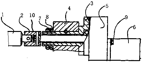
[0007] The present invention will be further explained below in conjunction with the accompanying drawings and embodiments.

[0008] Such as figure 1 As shown, a lead screw connection device includes a lead screw 1, the lead screw 1 is provided with a sleeve coupling 2, the sleeve coupling 2 is provided with a support sleeve 3, and the support sleeve 3 is provided with a bracket 4, and the support sleeve 3 is provided with a reduction box 5, and a stepping motor 6 is connected to the reduction box 5. The support sleeve 3 is matched with the bracket 4 through a nut 7 and a washer 8 , and the support sleeve 3 is connected with the bracket 4 through a pin shaft. The reduction box 5 is fixedly connected with the stepping motor 6 through a screw 9 . The screw 1 and the sleeve coupling 2 are fixedly connected through a pin 10 .


PUM


Abstract

The invention discloses a lead screw connection device, comprising a lead screw, a sleeve coupling is arranged on the lead screw, a supporting sleeve is sleeved on the sleeve coupling, and a bracket is arranged on the support sleeve , the support sleeve is provided with a reduction box, the reduction box is connected with a stepping motor, the support sleeve and the bracket are matched through nuts and washers, and the support sleeve and the bracket are connected through pin shafts. The reduction box is fixedly connected to the stepping motor through a screw, and the lead screw and sleeve coupling are fixedly connected through a pin shaft. The present invention has the advantages of simple structure, suitable for maintenance and stable connection.

Description

technical field [0001] The invention relates to a lead screw connection device. Background technique [0002] A CNC machine tool is an automatic machine tool equipped with a program control system, which can logically process the program specified by the control code or other symbolic instructions, decode it, express it in coded numbers, and input it into the CNC machine tool through the information carrier. device. After calculation and processing, various control signals are sent by the numerical control device to control the movement of the machine tool, and the parts are automatically processed according to the shape and size required by the drawing. CNC machine tools better solve complex, precise, small-batch and multi-variety parts processing problems, and are flexible and high-efficiency automatic machine tools. The connection between the lead screw and the motor on the CNC machine tool is particularly important, but the existing connection structure is complex and ...

Claims


Application Information

Patent Timeline
IPC IPC(8): B23Q5/44
CPCB23Q5/44
Inventor 李泳
Owner 李泳
Why Eureka
Try Eureka