Chemical vapor deposition furnace

A technology of chemical vapor deposition and furnace body, which is applied in the direction of gaseous chemical plating, metal material coating process, coating, etc. It can solve the problems of low product temperature, inconsistent quality, and failure to reach the deposition temperature, so as to improve the deposition effect , not easy to clog, solve the effect of clogging

Active Publication Date: 2018-03-09
ADVANCED FOR MATERIALS & EQUIP
View PDF5 Cites 10 Cited by
  • Summary
  • Abstract
  • Description
  • Claims
  • Application Information

AI Technical Summary

Problems solved by technology

Due to the intake structure of the existing deposition furnace, the carbon source gas directly enters the material tray at the bottom of the deposition chamber from the intake pipeline, and quickly enters the high-temperature area in the middle of the deposition furnace at a speed of 1-3 m / s, causing the deposition furnace The temperature of the product at the bottom is too low to reach the deposition temperature, and the carbon source gas quickly passes through the product at the bottom, before it can deposit on the product at the bottom, it goes to the product in the middle, resulting in poor deposition effect of the product at the bottom in the deposition furnace Good, so that the quality of products at different positions in the deposition furnace is inconsistent, or the quality of different parts of the same product is inconsistent

Method used


Image

  • Chemical vapor deposition furnace

Examples


Embodiment Construction

[0020] In order to enable those skilled in the art to better understand the technical solutions in the present application, the technical solutions in the embodiments of the present application will be clearly and completely described below in conjunction with the drawings in the embodiments of the present application. Obviously, the described The embodiments are only some of the embodiments of the present application, but not all of them. Based on the embodiments in this application, all other embodiments obtained by persons of ordinary skill in the art without creative efforts shall fall within the scope of protection of this application.

[0021] First of all, it should be noted that the “outside of the gas distributor” mentioned in this application may or may not be on the gas distributor.

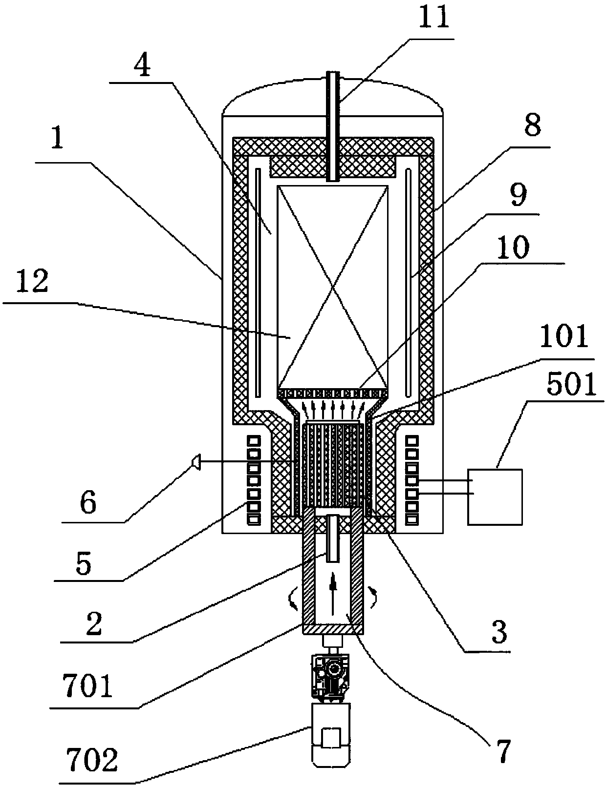
[0022] Such as figure 1 As shown, a chemical vapor deposition furnace provided in this embodiment includes a furnace body 1 and an air intake device arranged at the bottom of the furn...


PUM


Abstract

The invention discloses a chemical vapor deposition furnace. The chemical vapor deposition furnace comprises a furnace body and a gas inlet device arranged at the bottom of the furnace body, wherein the gas inlet device comprises a main gas inlet pipeline, a gas distribution device and a heater; the main gas inlet pipeline is communicated with the gas distribution device; the gas distribution device is communicated with a furnace chamber in the furnace body; the gas distribution device is used for uniformly distributing a gas flow into the furnace chamber; the heater is arranged at the outer part of the gas distribution device; the heater is used for heating the gas distribution device. According to the chemical vapor deposition furnace disclosed by the invention, carbon source gas entersfrom the main gas inlet pipeline and is dispersed into the furnace chamber through the gas distribution device; the gas distribution device can be used for uniformly distributing gas in a bottom spaceof the furnace chamber and buffering the speed of the gas flow, so that the gas flow can sufficiently react with a product at the bottom of the furnace chamber; the heater is arranged on the gas distribution device and can be used for pre-heating the entered carbon source gas so that the carbon source gas is sufficiently cracked and volatilized at the bottom of the furnace chamber; the product atthe bottom is subjected to deposition reaction so that a whole deposition effect of the product is improved.

Description

technical field [0001] The invention belongs to the technical field of chemical vapor deposition equipment, and in particular relates to a chemical vapor deposition furnace. Background technique [0002] Carbon-carbon composite material is a high-performance composite material with carbon fiber reinforced carbon matrix. It has the characteristics of high strength, corrosion resistance, and strong designability. It has been widely used in many fields such as aerospace, aviation, and transportation. The development of technology and the advancement of science and technology have higher requirements for the quality of carbon-carbon composite products. [0003] Chemical vapor deposition is a process widely used in the production of carbon-carbon composites. Most of the existing chemical vapor deposition furnaces or deposition systems pass carbon source gas into the deposition furnace from the bottom of the deposition furnace through multi-channel air intake pipelines, and the c...

Claims


Application Information

Patent Timeline
Patent Type & Authority Applications(China)
IPC IPC(8): C23C16/455C23C16/26
CPCC23C16/26C23C16/455C23C16/45561
Inventor 胡祥龙戴煜杨毅成
Owner ADVANCED FOR MATERIALS & EQUIP
Why Eureka
Try Eureka