Continuous chemical vapor deposition furnace and working method thereof

A chemical vapor deposition, deposition furnace technology, applied in gaseous chemical plating, metal material coating process, coating and other directions, can solve the problems of inconsistent product quality, failure to reach deposition temperature, long preparation time, etc. Uniformity, time saving, quality improvement

Pending Publication Date: 2021-03-26
SHANGHAI QI JIE CARBON MATERIALS
View PDF4 Cites 2 Cited by
  • Summary
  • Abstract
  • Description
  • Claims
  • Application Information

AI Technical Summary

Problems solved by technology

Due to the intake structure of the existing deposition furnace, the carbon source gas directly enters the material tray at the bottom of the deposition chamber from the intake pipeline, and quickly enters the high-temperature area in the middle of the deposition furnace at a speed of 1-3 m / s, causing the deposition furnace The temperature of the product at the bottom is too low to reach the deposition temperature, and the carbon source gas quickly passes through the product at the bottom, before it can deposit on the product at the bottom, it goes to the product in the middle, resulting in poor deposition effect of the product at the bottom in the deposition furnace Good, so that the quality of products at different positions in the deposition furnace is inconsistent, or the quality of different parts of the same product is inconsistent
[0004] And because the existing deposition furnace is a single furnace chamber, generally there is no preheating and cooling steps when the preform is placed in the deposition furnace for preparation, and the preform is directly heated and cooled in the furnace chamber, resulting in a single deposition furnace during preparation. The resulting preparation takes a long time and has low efficiency, so it is of great significance to provide a continuous chemical vapor deposition furnace and its working method

Method used


Image

  • Continuous chemical vapor deposition furnace and working method thereof
  • Continuous chemical vapor deposition furnace and working method thereof
  • Continuous chemical vapor deposition furnace and working method thereof

Examples


specific Embodiment 1

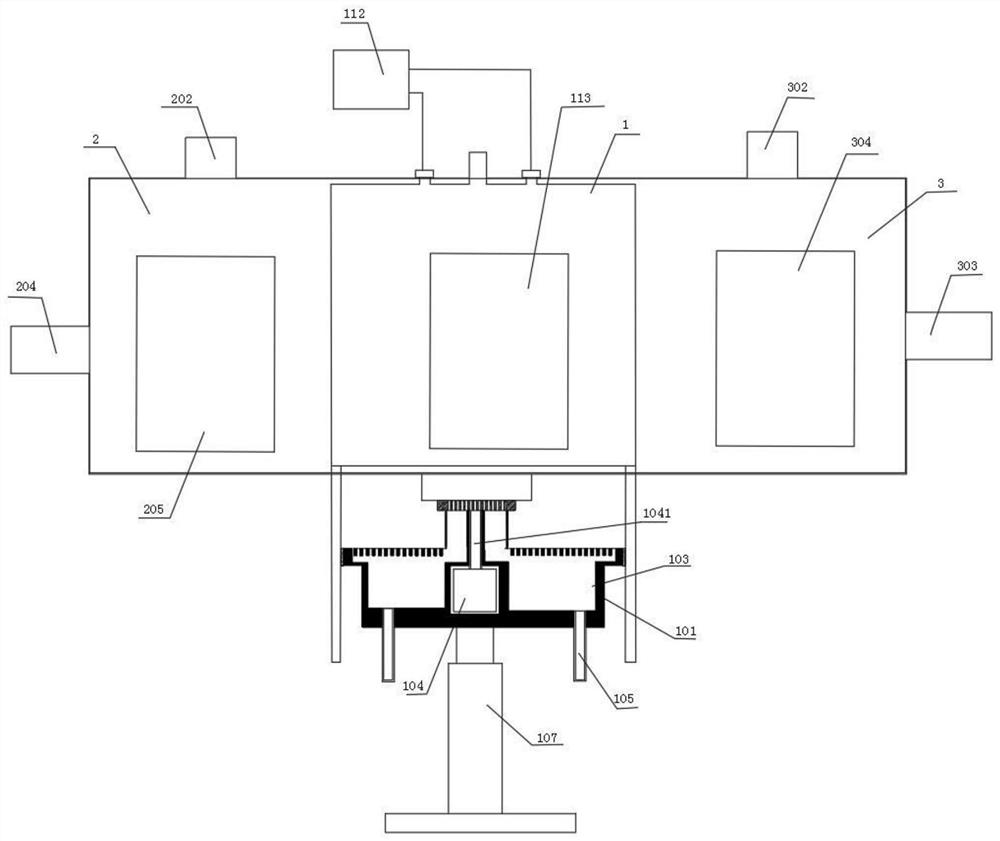
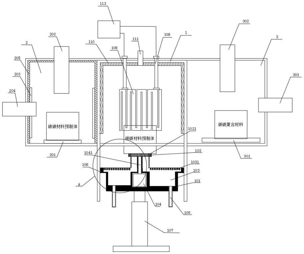
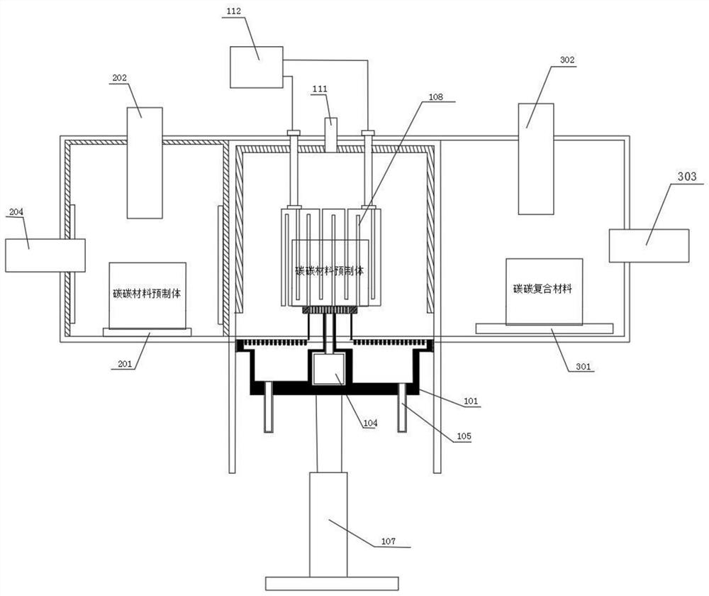
[0038] see Figure 1-5 As shown, in a continuous chemical vapor deposition furnace of the present invention, the deposition furnace is successively divided into a preparation area 2, a deposition area 1 and a cooling area 3 by partitions;

[0039] The deposition area 1 includes a furnace body, a lifting platform 101 installed below the furnace body and moving up and down in the furnace cavity of the furnace body, a rotating platform 102 arranged on the upper surface of the lifting platform 101 for carrying preforms, and a rotating platform 102 installed on the lifting platform 101. The power box in the inside, the lifting mechanism 107 that is arranged under the lifting table 101 for lifting the lifting table 101, the heater 108 or the induction coil that is installed on the upper part of the furnace cavity and corresponds to the rotating carrier table 102; There is a rotating mechanism 104, and the rotating mechanism 104 is provided with a rotating shaft 1041 connected to the...

specific Embodiment 2

[0054] The difference between this specific embodiment and embodiment 1 is that

[0055] Wherein, the heater 108 adopts any one of a circular integral heater, a circular splicing heater, a square integral heater or a square splicing heater; the preferred circular splicing heater in this embodiment; the heater 108 is made of graphite, carbon For other high temperature resistant materials such as carbon or tungsten molybdenum, carbon-carbon material is preferred in this embodiment; the rotary bearing table 102 adopts an axial flow type or a non-axial flow type, and this embodiment is preferably an axial flow type, which is a prior art and needs no further description.

[0056] Beneficial effect:

[0057] 1. The continuous chemical vapor deposition furnace of the present invention adopts a continuous structure consisting of a preheating zone, a deposition zone and a cooling zone, and it can be achieved that the same deposition furnace has three preparations in three zones at the ...


PUM


Abstract

The invention discloses a continuous chemical vapor deposition furnace and a working method thereof, and relates to the field of composite material manufacturing equipment. A preparation area, a deposition area and a cooling area are sequentially arranged in the continuous chemical vapor deposition furnace; the deposition area comprises a lifting platform, at least one rotary bearing platform anda heater corresponding to the rotary bearing platform; and a first sealing door, a second sealing door and a third sealing door are respectively arranged outside the preparation area, the deposition area and the cooling area. According to the continuous chemical vapor deposition furnace and the working method thereof, three preparation parts in the same deposition furnace can be preheated, deposited and cooled in three areas respectively and are continuously converted in sequence, so that the preparation efficiency of a composite material of the single deposition furnace is greatly improved, and the time is saved. Due to the structural design of the deposition area, a bearing plate loaded with a carbon fiber preform can rotate in the heating preparation process, the uniformity of the action of internal mixed gas and heating temperature on the surface of the bearing plate is kept, and the quality of a finished product prepared from the carbon fiber preform is improved.

Description

technical field [0001] The invention belongs to the field of composite material manufacturing equipment, in particular to a continuous chemical vapor deposition furnace and a working method of the continuous chemical vapor deposition furnace. Background technique [0002] Composite material is a high-performance composite material of carbon fiber reinforced carbon matrix. It has the characteristics of high strength, corrosion resistance, and strong designability. It has been widely used in many fields such as aerospace, aviation, and transportation. With the development of society and The advancement of science and technology has higher requirements for the quality of composite products. [0003] Chemical vapor deposition is a process widely used in the production of composite materials. Most of the existing chemical vapor deposition furnaces or deposition systems pass carbon source gas into the deposition furnace from the bottom of the deposition furnace through multi-chan...

Claims


Application Information

Patent Timeline
Patent Type & Authority Applications(China)
IPC IPC(8): C23C16/54C23C16/56C23C16/02C23C16/26C23C16/458
CPCC23C16/54C23C16/26C23C16/0209C23C16/56C23C16/4584
Inventor 申富强王景珍
Owner SHANGHAI QI JIE CARBON MATERIALS
Why Eureka
Try Eureka