Bladeless fan

A bladeless fan and air cavity technology, applied in liquid fuel engines, non-volume pumps, mechanical equipment, etc., can solve the problems of low production efficiency, air transmission loss, non-disassembly, etc., to improve the air supply effect and improve the noise problems, effects of avoiding transmission loss

Pending Publication Date: 2018-03-09
应辉
View PDF7 Cites 8 Cited by
  • Summary
  • Abstract
  • Description
  • Claims
  • Application Information

AI Technical Summary

Problems solved by technology

[0003] 1. When working, the airflow is inhaled from the side of the base and finally ejected from the annular exhaust port. The direction of airflow transmission in the middle has been changed many times, which will easily lead to transmission loss of airflow and eventually affect the air supply volume of the fan. , The air collection structure between the air outlet end of the existing base and the annular nozzle adopts a sudden change design, which is not conducive to the balance and stability of airflow transmission. When this airflow blows to the human body, it is easy to produce a dramatic wind shock, which is not stable , making people feel uncomfortable
[0004] 2. Since the air inlet is set on the side surface of the base, and there is no reasonable sound-absorbing structure, the noise emitted by the impeller when it sucks the external air diffuses outward through the air inlet almost without any barr

Method used


Image

  • Bladeless fan
  • Bladeless fan
  • Bladeless fan

Examples


Example Embodiment

[0035] The present invention will be further described in detail below in conjunction with the embodiments given in the drawings.

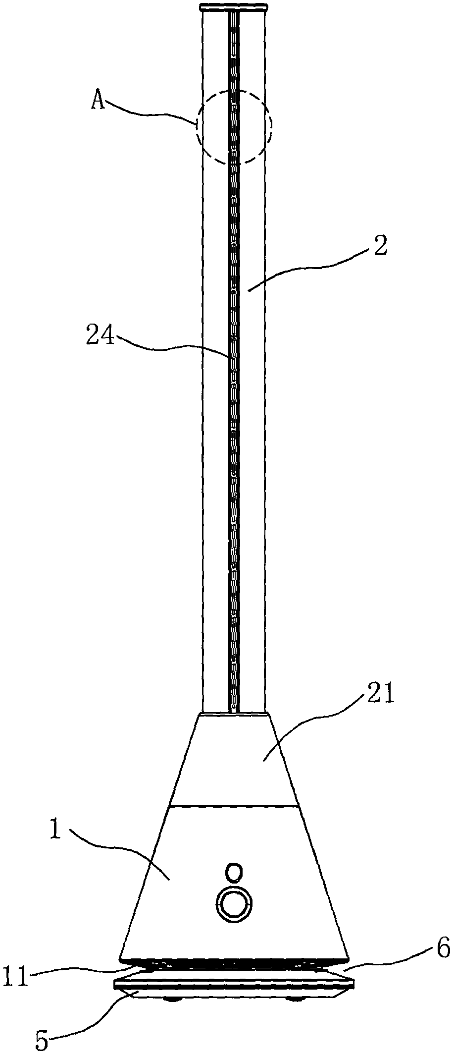
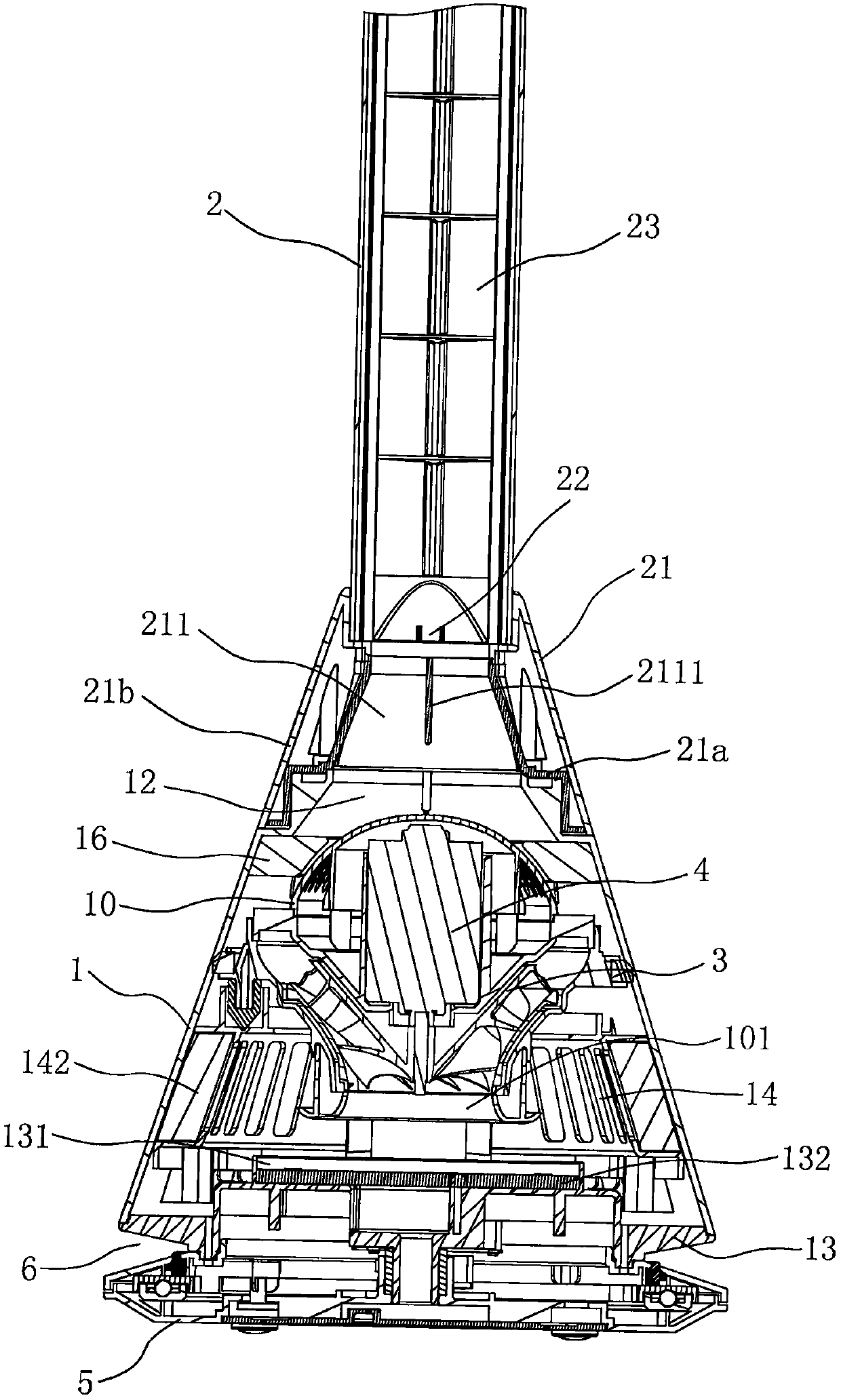
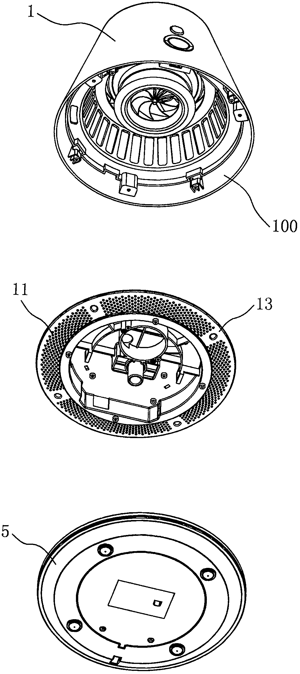
[0036] Such as Figure 1 to Figure 10 As shown, the bladeless fan of the present invention includes a base body 1 and an air outlet 2 provided at the upper end of the base body 1. The bottom of the base body 1 is provided with an air inlet 11 (and as another alternative embodiment, it is also The air inlet 11 can be arranged on the side of the base 1), the base 1 is provided with an impeller 3 and a motor 4 for generating air flow, the upper end of the base 1 is provided with a horn-shaped air outlet 12 with a small upper and a large lower end, and the lower end of the air outlet 2 A connecting sleeve 21 is provided. The connecting sleeve 21 is provided with a horn-shaped air inlet 211 with a small upper and a large lower end. The large end of the horn-shaped air inlet 211 is connected with the small end of the horn-shaped air outlet 12 of the base b...


PUM


Abstract

The invention relates to a bladeless fan which comprises a base and a fan chimney arranged at the upper end of the base. An air inlet is formed in the side face or the bottom of the base, an impellerand a motor for generating airflow are arranged in the base, a big-end-down flared air outlet is formed in the upper end of the base, a connecting sleeve is arranged at the lower end of the fan chimney, a big-end-down flared air inlet hole is formed in the connecting sleeve, a large end of the flared air inlet hole is connected with a small end of the flared air outlet of the base, a small end ofthe flared air inlet hole is connected with a bottom opening of the fan chimney, a vertical channel for receiving the airflow is arranged in the fan chimney, the center of the vertical channel and thecenters of the flared air inlet hole and the flared air outlet are positioned on the same straight line, at least one row of longitudinally distributed air outlet narrow slits are formed in the surface of the fan chimney, and the airflow received by the vertical channel is jetted outwards from the air outlet narrow slits. The bladeless fan has the advantages of balanced and stable airflow, stability, comfort, high flow, strong wind power, reasonable structure, attractive appearance, low noise, convenience in disassembly and assembly and the like.

Description

technical field [0001] The invention relates to the field of fans, in particular to a bladeless fan. Background technique [0002] In the prior art, the bladeless fan generally includes a base and an annular nozzle supported by the base, an air inlet is provided on the side of the base, an airflow channel and an impeller and a motor for generating airflow are arranged in the base, and the base The air outlet end of the ring nozzle is connected with the inlet end of the annular nozzle, and the annular nozzle is provided with an annular channel for receiving air flow and an annular exhaust port for jetting air flow, and the annular nozzle is also provided with a ring for guiding external air to the annular exhaust port Nearby, the annular opening that mixes with the airflow ejected from the annular exhaust port. The structural nozzle has the following disadvantages when users use it: [0003] 1. When working, the airflow is inhaled from the side of the base and finally eject...

Claims


Application Information

Patent Timeline
IPC IPC(8): F04B41/06F04B39/14F04D25/08F04D29/52F04D29/66F04D29/64F04F5/16F04F5/46
CPCF04B39/14F04B41/06F04D25/08F04D29/522F04D29/646F04D29/664F04F5/16F04F5/46
Inventor 应辉
Owner 应辉
Why Eureka
Try Eureka