Heat exchanger core for heat exchange between three fluids
A three-fluid, heat exchanger technology, applied in the direction of heat exchanger types, indirect heat exchangers, heat exchange equipment, etc., can solve the problems of different fluid working fluid cleanliness, blockage, and shortening the service life of heat exchangers
- Summary
- Abstract
- Description
- Claims
- Application Information
AI Technical Summary
Problems solved by technology
Method used
Image

Examples
Embodiment 1
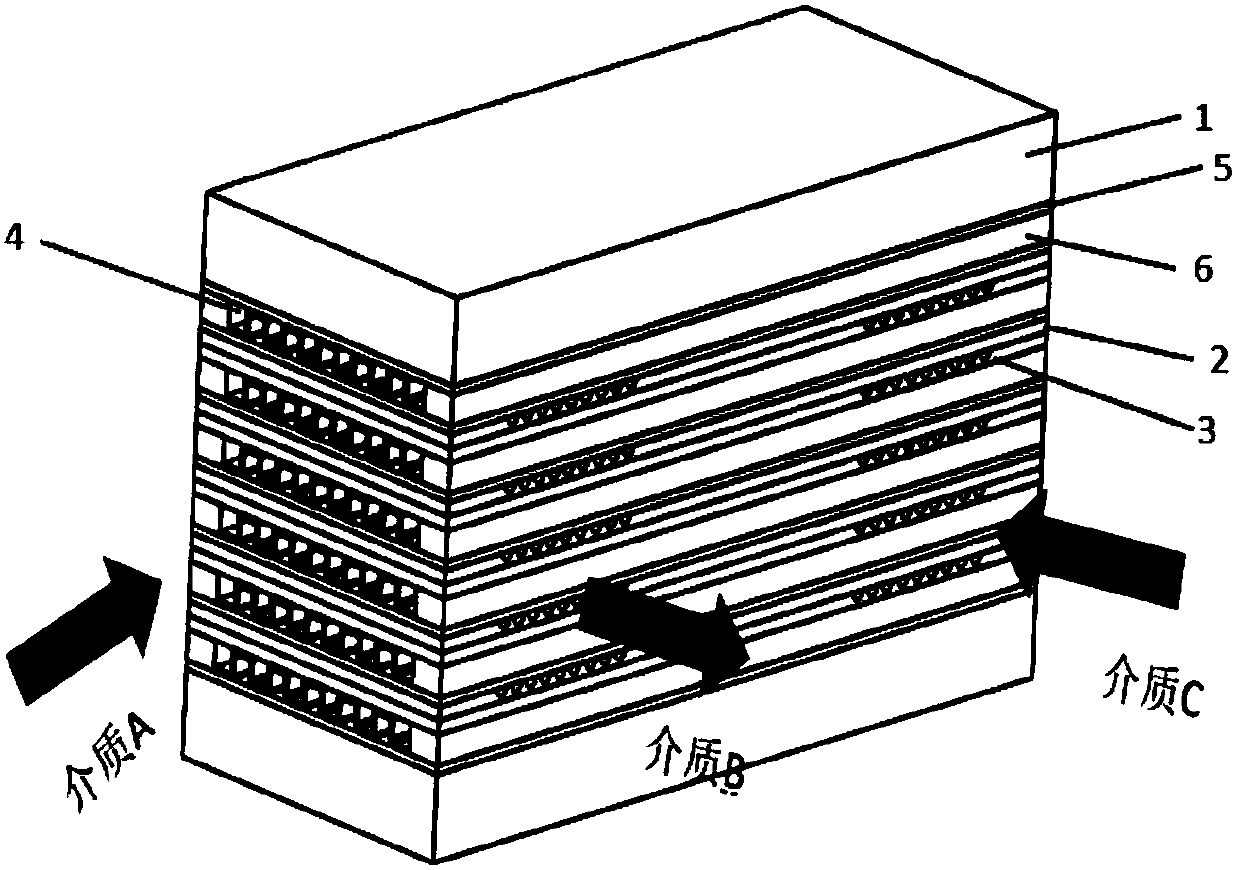
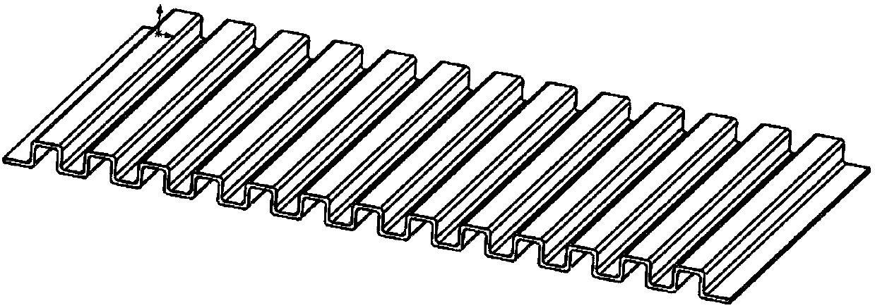
[0044] combine Figure 1-7 , this embodiment provides a heat exchanger core for heat exchange of three fluids, including two cover plates 1, a first etched plate 2, a second etched plate 3, a formed plate 4, and a partition 5 , baffle plate 6; forming plate 4 and partition 5 constitute structural unit A, first etched plate 2 and second etched plate 3 constitute structural unit B; structural unit A and structural unit B are between two cover plates 1 Alternately stacked; the non-etched surface of the first etched sheet 2 is abutted with the etched surface of the second etched sheet 3; the etched surface of the first etched sheet 2 is abutted with the partition 5 of the adjacent structural unit A; molding One side of the plate 4 is in contact with the partition 5, and the other side is in contact with the non-etched surface of the second etched plate 3 of the adjacent structural unit B; a partition 5 is arranged between the cover plate 1 and the forming plate 4; A partition 5 i...
Embodiment 2
[0051] The difference between this embodiment and Embodiment 1 is that two cover plates 1, the first etched plate 2, the second etched plate 3, the formed plate 4, the partition plate 5 and the baffle plate 6 are processed into a cuboid; the formed plate 4 is a rectangle, and the inlet and outlet of its flow channel are arranged on the long sides of the rectangle; the first etched sheet 2 and the second etched sheet 3 are all rectangular, and the inlets and outlets of their flow channels are all arranged on the wide sides of the rectangle and Stagger each other.
Embodiment 3
[0053] The difference between this embodiment and embodiment 1 is that two cover plates 1, the first etched plate 2, the second etched plate 3, the forming plate 4, the partition plate 5 and the baffle plate 6 are processed into a cube; The first etched sheet 2, the second etched sheet 3 and the formed sheet 4 are all square, and the inlets and outlets of their flow channels are arranged on different sides of the square and staggered from each other.
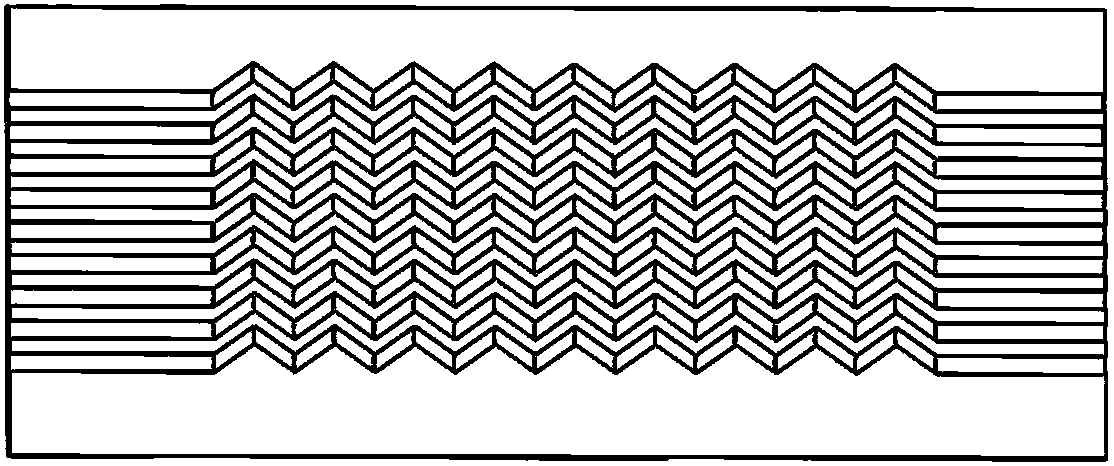
[0054] The etched sheets (the first etched sheet 2 and the second etched sheet 3) described in the present invention process flow passages of different forms on the sheets by chemical etching, and the flow passages can be straight passages or flow passages. Zigzag flow channel, the flow channel inlet and outlet of the etched plate can be located at any position around the plate through the guide channel, the etched plate 3 is suitable for the working medium with a high degree of fluid cleanliness, and the flow channel size proces...
PUM
 Abstract
Description
Claims
Application Information
 - R&D
- Intellectual Property
- Life Sciences
- Materials
- Tech Scout
- Unparalleled Data Quality
- Higher Quality Content
- 60% Fewer Hallucinations
Browse by: Latest US Patents, China's latest patents, Technical Efficacy Thesaurus, Application Domain, Technology Topic, Popular Technical Reports.
© 2025 PatSnap. All rights reserved.Legal|Privacy policy|Modern Slavery Act Transparency Statement|Sitemap|About US| Contact US: help@patsnap.com