

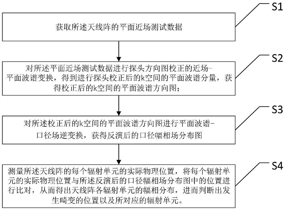
A method for diagnosing the distorted position of the aperture amplitude and phase field of an antenna array
A technology for diagnosing antennas and antenna arrays, applied to radio wave measurement systems, instruments, etc., can solve the problems of practical limitations, use limitations, labor and time costs, etc., to improve the quality of the pattern, reduce diagnostic errors, and strengthen engineering The effect of practicality
- Summary
- Abstract
- Description
- Claims
- Application Information
AI Technical Summary
Problems solved by technology
Method used
Image

Examples
Embodiment 1
[0185] In order to diagnose the accuracy of the diagnostic method provided by the present invention to the failure unit in the front, a certain L-band vertical linearly polarized antenna was tested in a dark room. The number of horizontal units of the tested front is 42, the horizontal unit spacing is 0.138m, the number of vertical units is 1, and the test frequency is 990Mhz. At the same time, the failure units were introduced at the positions of the 36th and 40th units, and the test was carried out, and the inversion diagnosis was carried out by using the program algorithm. The results and analysis obtained are as follows:
[0186] Figure 6 is the three-dimensional magnitude pattern, Figure 7 and Figure 8 They are the horizontal amplitude distribution curve and the horizontal phase distribution curve of the aperture field respectively. Figure 9 It is a graph of the amplitude distribution curve positioned to each unit.
[0187] From Figure 7 and Figure 8 It can be...
Embodiment 2
[0189]A faulty unit diagnostic test is carried out on an S-band array antenna. The test frequency is 3140MHz, the number of horizontal units is 128, and the unit spacing is 0.046m. Introduce failure units directly at the 5th and 100th unit positions for near-field active state testing. Utilize the present invention to carry out inversion diagnosis result and analysis to test result as follows:
[0190] Figure 10 , Figure 11 and Figure 12 They are the aperture field amplitude distribution graph, the aperture field horizontal amplitude distribution curve, and the aperture field horizontal phase distribution graph. Figure 13 It is a graph of the amplitude distribution curve positioned to each unit.
[0191] Figure 10 to Figure 12 It reflects the aperture field distribution after the failure unit is introduced, and the position of the failure unit can be basically determined. Figure 13 The positioning curve in the figure can accurately diagnose the position of the fail...
PUM
 Abstract
Description
Claims
Application Information