A battery core spacing mechanism and a device for feeding battery cores into casings

A cell and distance separation technology, which is applied in the direction of battery assembly, non-aqueous electrolyte storage battery, and electrolyte storage battery manufacturing, can solve problems such as increased instability factors, uncontrollable free state, and hidden dangers in stability, and achieves battery cell The effect of increased quantity, strong compatibility, and stable and controllable actions

Pending Publication Date: 2018-03-09
常州华数锦明智能装备技术研究院有限公司
View PDF8 Cites 0 Cited by
  • Summary
  • Abstract
  • Description
  • Claims
  • Application Information

AI Technical Summary

Problems solved by technology

[0004] Suppose D,D 1 Definitely, the difference between the batteries arranged before and after the spacing is Δ=N·D 1 -N·D, it can be found that with the increase of the number of cells N, the difference Δ will become larger and larger, and when the difference Δ accumulates to a certain value, the cells will not be able to accurately roll into the fixed distance block
[0005] Assuming that D and N are fixed, the difference between the batteries arranged before and after the spacing is Δ=N·D 1 -N·D, it can be found that the distance between the center of the battery cell and the value D 1 As the value increases, the difference Δ will become larger and larger, and when the difference Δ accumulates to a certain value, the battery will not be able to accurately roll into the fixed distance block
[0006] Due to the free rolling by the gravity of the battery cell, the attitude of the battery cell in the rolling process is in a free state and cannot be controlled, and there are hidden dangers in the stability. With the increase of the number of battery cells, the instability factors increase

Method used


Image

  • A battery core spacing mechanism and a device for feeding battery cores into casings
  • A battery core spacing mechanism and a device for feeding battery cores into casings
  • A battery core spacing mechanism and a device for feeding battery cores into casings

Examples


Embodiment 1

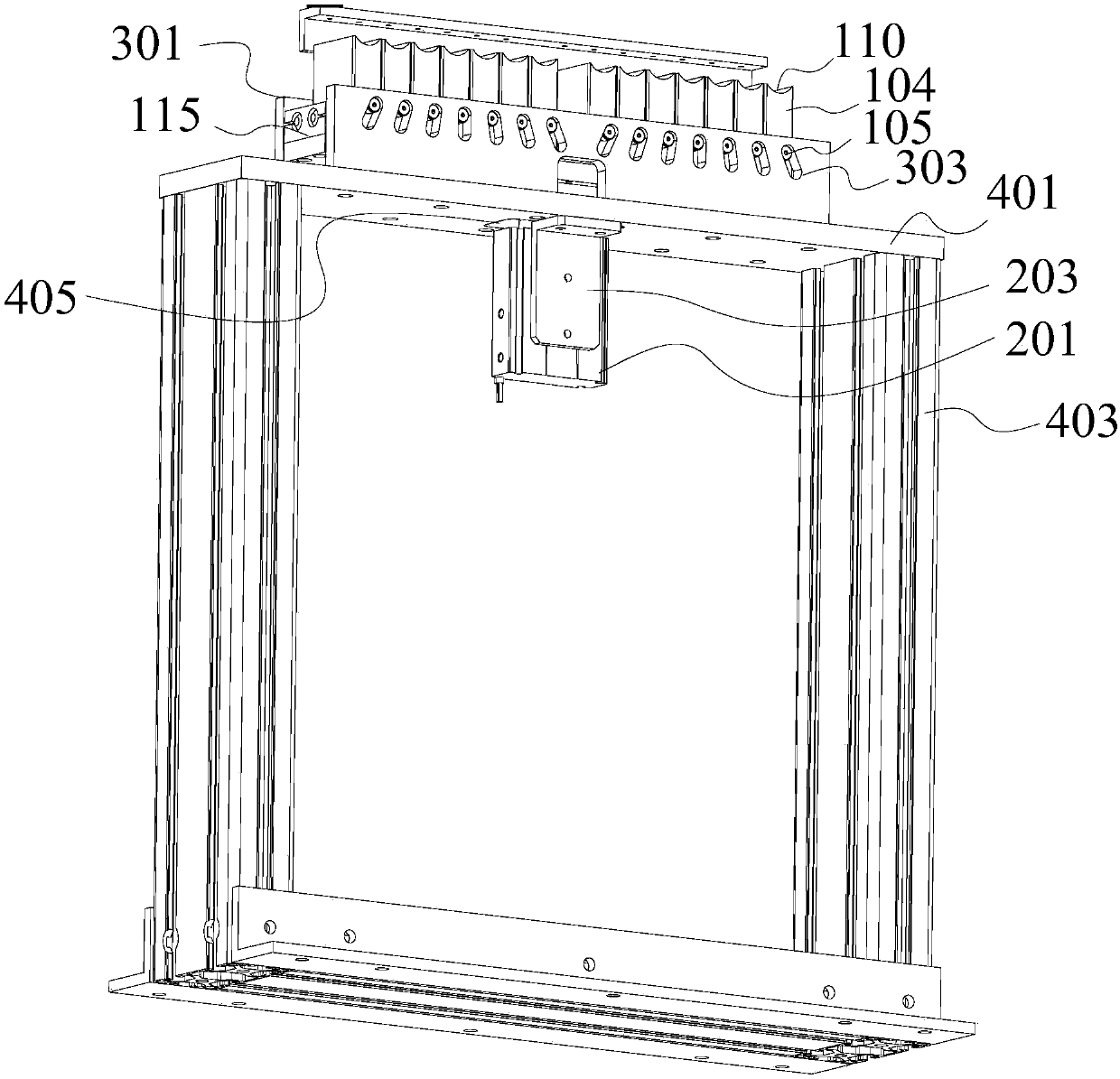
[0041] see Figure 3 to Figure 5 As shown, the present invention provides a cell separation mechanism, comprising: a cell loading assembly, a separation driving assembly and a guide assembly.

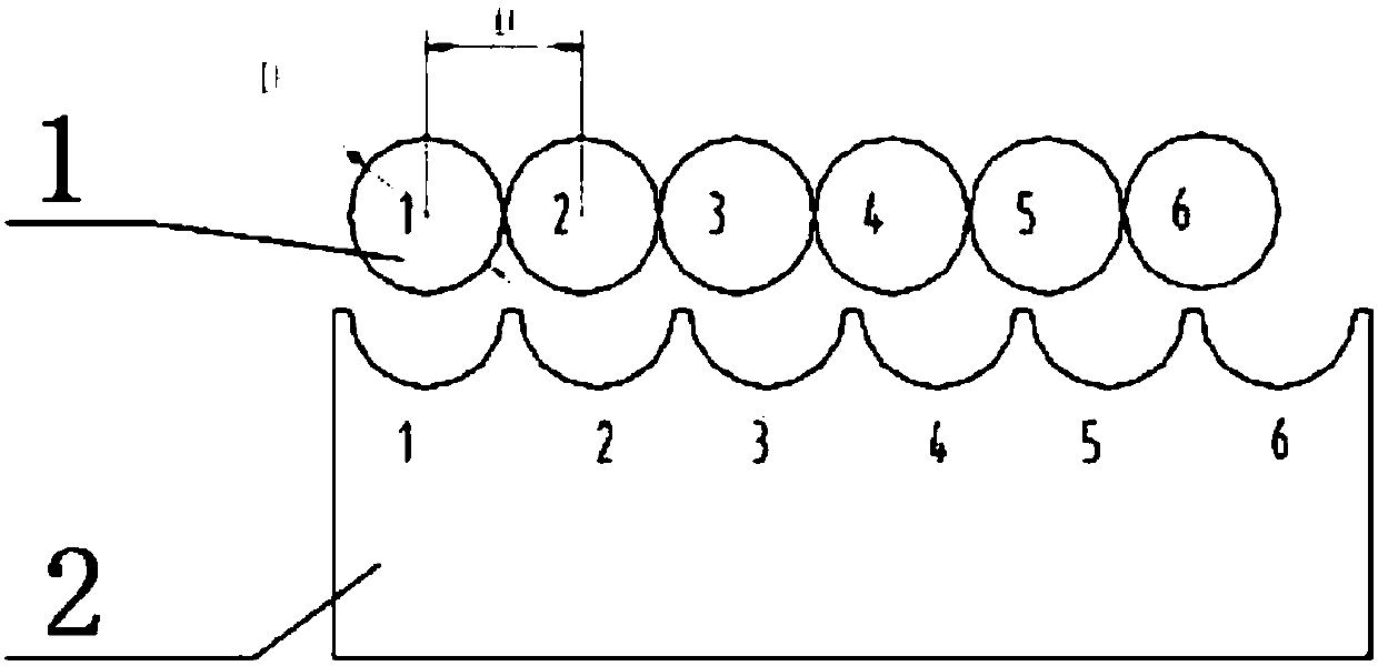
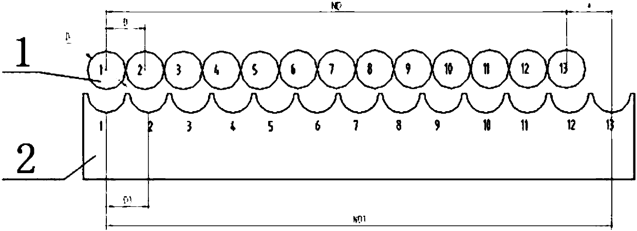
[0042] The battery cell loading assembly includes a linear guide rail 101 and a plurality of linearly arranged battery cell loading members 104 that are slidably connected to the linear guide rail 101 and are suitable for loading cells; A cam follower 105 is provided. In this embodiment, the linear guide 101 adopts, for example, but not limited to, a linear optical axis, and the corresponding cell loading member 104 is connected with the linear optical axis through the linear bearing 102 , that is, the cell loading member 104 is provided with a mounting suitable for the linear bearing 102 . Mounting holes.

[0043] The distance-separated drive assembly includes a driver 201 disposed at the middle position of the bottom of the linear guide rail 101 and adapted to drive the linear guide...

Embodiment 2

[0053] Based on the cell separation mechanism of Embodiment 1, this embodiment provides a battery cell insertion device, including the cell separation mechanism of Embodiment 1.


PUM


Abstract

The invention relates to the technical field of lithium battery manufacturing, and particularly relates to a battery core spacing mechanism and a device for feeding battery cores into casings. The battery core spacing mechanism includes a battery core loading assembly, a spacing drive assembly and a guide assembly. The battery core loading assembly includes a linear guideway and a plurality of battery core loading members arranged in a straight line, slidingly connected to the linear guideway and used for loading battery cores. Outside end surfaces along the length direction of the battery core loading members are provided with cam followers. The spacing drive assembly includes a driver disposed at the middle of the bottom of the linear guideway and driving the linear guideway to move up and down. The guide assembly includes a group of guide plates disposed at two end surfaces along the length direction of the battery core loading assembly respectively. The guide plates are provided with waist-shaped slots into which the cam followers can be inserted for each battery core loading member. The spacing states of the device for feeding battery cores into casings and for core distribution and spacing, and a machine for feeding battery cores into casings are stable and controllable.

Description

technical field [0001] The invention relates to the technical field of lithium battery manufacturing, and in particular, to a cell separation mechanism and a cell insertion device. Background technique [0002] see figure 1 As shown in the figure, the current state of incoming cells is that one cell is placed close to one another. The cell is separated by a fixed spacer block, the entrance of the spacer block is used as a guide, and a slot with a fixed distance is opened at the bottom. Roll the cells into the slot to achieve cell separation. [0003] see figure 2 As shown, the diameter of the cells is D, the radius is D, the number of cells is N, and the incoming state of the cells is one close to the other. It can be seen that the center distance of the cells is D. If it is assumed that the distance between the cells is separated, the The center-to-center distance is D 1 (D 1 >D); [0004] Suppose D, D 1 Certainly, the difference between the cells arranged before...

Claims


Application Information

Patent Timeline
Patent Type & Authority Applications(China)
IPC IPC(8): H01M10/058H01M10/04H01M10/0525
CPCH01M10/0404H01M10/0525H01M10/058Y02E60/10Y02P70/50
Inventor 王玉宝刘保柱邓少武吴岩申灿
Owner 常州华数锦明智能装备技术研究院有限公司
Why Eureka
Try Eureka