Multifunctional unmanned aerial vehicle

An unmanned aerial vehicle, multi-functional technology, applied in the field of unmanned aerial vehicles, can solve the problems of lack of multi-functional unmanned aerial vehicles, and achieve the effect of simple structure and reasonable structure

Inactive Publication Date: 2018-03-13
蓝振宁
View PDF6 Cites 0 Cited by
  • Summary
  • Abstract
  • Description
  • Claims
  • Application Information

AI Technical Summary

Problems solved by technology

[0003] At present, the drones on the market are booming, but th

Method used


Image

  • Multifunctional unmanned aerial vehicle

Examples


Embodiment Construction

[0018] Below in conjunction with embodiment the present invention is described in further detail:

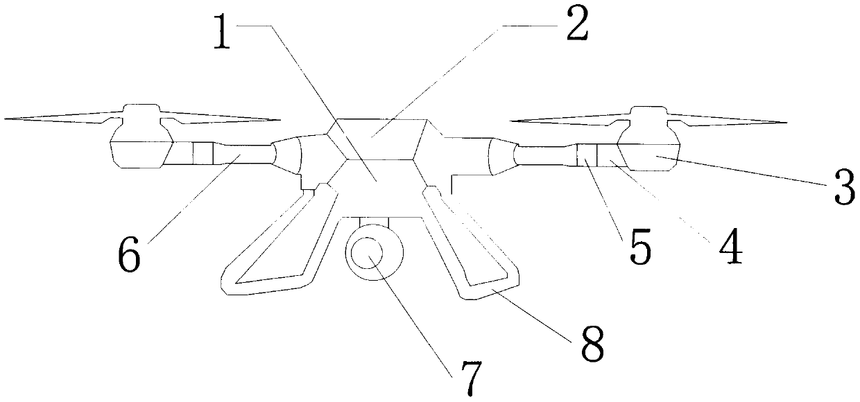
[0019] A multifunctional unmanned aerial vehicle, comprising a host 1, a solar collector plate 2, an LED light 3, an infrared distance detector 4, a buzzer 5, a telescopic rod 6, a camera 7, and a bracket 8. The upper surface of the host 1 is A solar heat collecting plate 2 is provided, and a telescopic rod 6 is arranged around it, and a camera 7 and a bracket 8 are arranged at the lower end;

[0020] The solar thermal collector plate 2 is made of lightweight film material.

[0021] The infrared distance detector 4 is spherical and can detect the distance between other objects and the drone in all directions.

[0022] The support 8 is foldable.


PUM


Abstract

The invention relates to a multifunctional unmanned aerial vehicle and relates to the technical field of the multifunctional unmanned aerial vehicle. The multifunctional unmanned aerial vehicle comprises a main vehicle, solar heat collection plates, LED lights, an infrared ray distance detector, a singing device, telescopic poles, a camera and a bracket, wherein the solar heat collection plates are arranged on the upper surface of the main vehicle, the telescopic poles are arranged on all around the main vehicle, and the camera and the bracket are arranged at the lower end of the main vehicle;and the LED lights, the infrared ray distance detector and the singing device are arranged at the tail ends of the telescopic poles in sequence. The multifunctional unmanned aerial vehicle is simpleand reasonable in structure and has characteristics of camera shooting, distance measurement, singing and guidance.

Description

technical field [0001] The invention relates to a multifunctional unmanned aerial vehicle and relates to the technical field of unmanned aerial vehicles. Background technique [0002] Unmanned aircraft is referred to as "UAV" for short, and the English abbreviation is "UAV". It is an unmanned aircraft controlled by radio remote control equipment and its own program control device. From a technical point of view, it can be divided into: unmanned fixed-wing aircraft, unmanned vertical take-off and landing aircraft, unmanned airship, unmanned helicopter, unmanned multi-rotor aircraft, unmanned parawing aircraft, etc. [0003] The unmanned aerial vehicle on the market is developing vigorously at present, but lacks a kind of multifunctional unmanned aerial vehicle, satisfies people's demand. Contents of the invention [0004] 1. Technical problems to be solved: [0005] The technical problem to be solved by the present invention is to provide a multifunctional unmanned aerial...

Claims


Application Information

Patent Timeline
IPC IPC(8): B64C39/02B64D47/00B64D47/08
CPCB64C39/02B64D47/00B64D47/08
Inventor 蓝振宁
Owner 蓝振宁
Why Eureka
Try Eureka