Impeller type washing machine
A technology of pulsator washing machine and sealing disc, which is applied to other washing machines, washing machines with containers, washing devices, etc., which can solve the problems of water waste, secondary pollution of clothes, bacterial growth, etc., and achieve the effect of saving water resources and reducing waste
- Summary
- Abstract
- Description
- Claims
- Application Information
AI Technical Summary
Problems solved by technology
Method used
Image

Examples
Embodiment 1
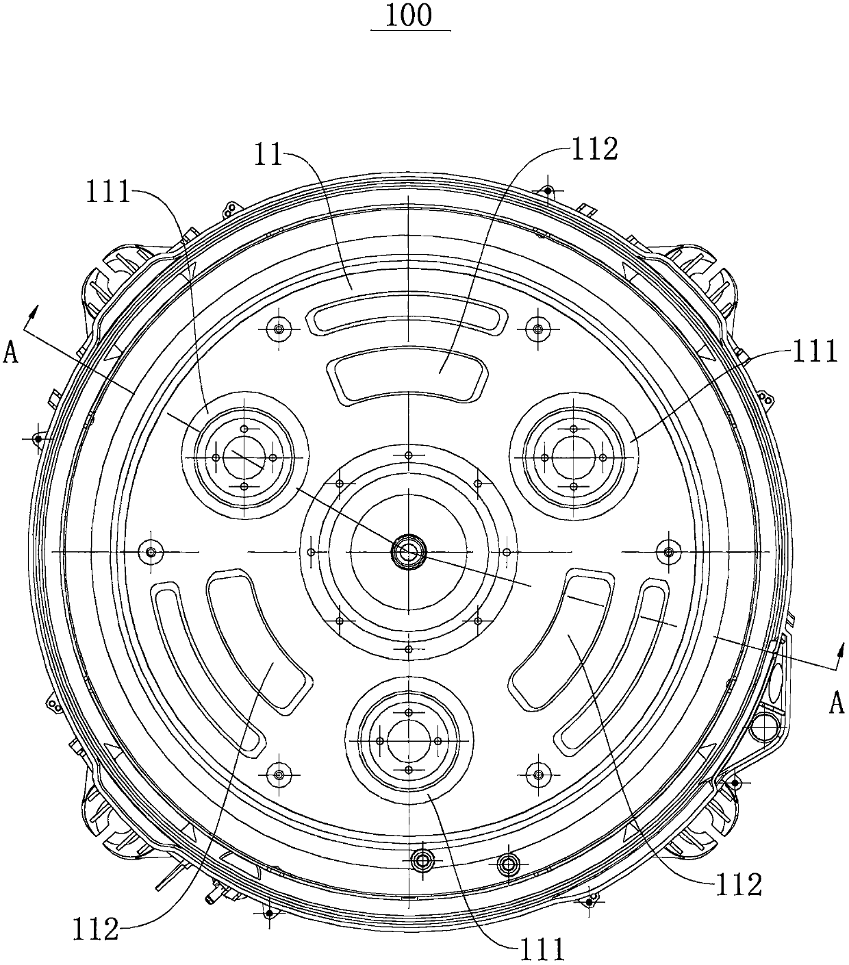
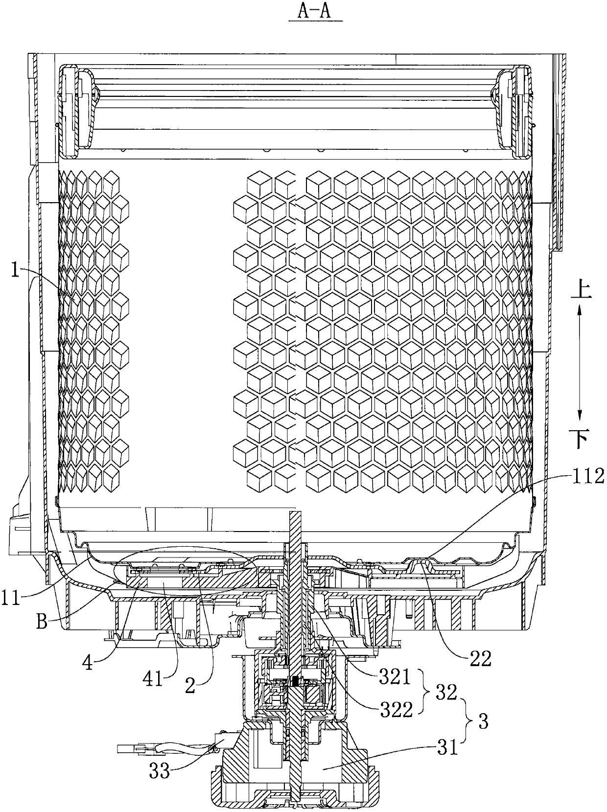
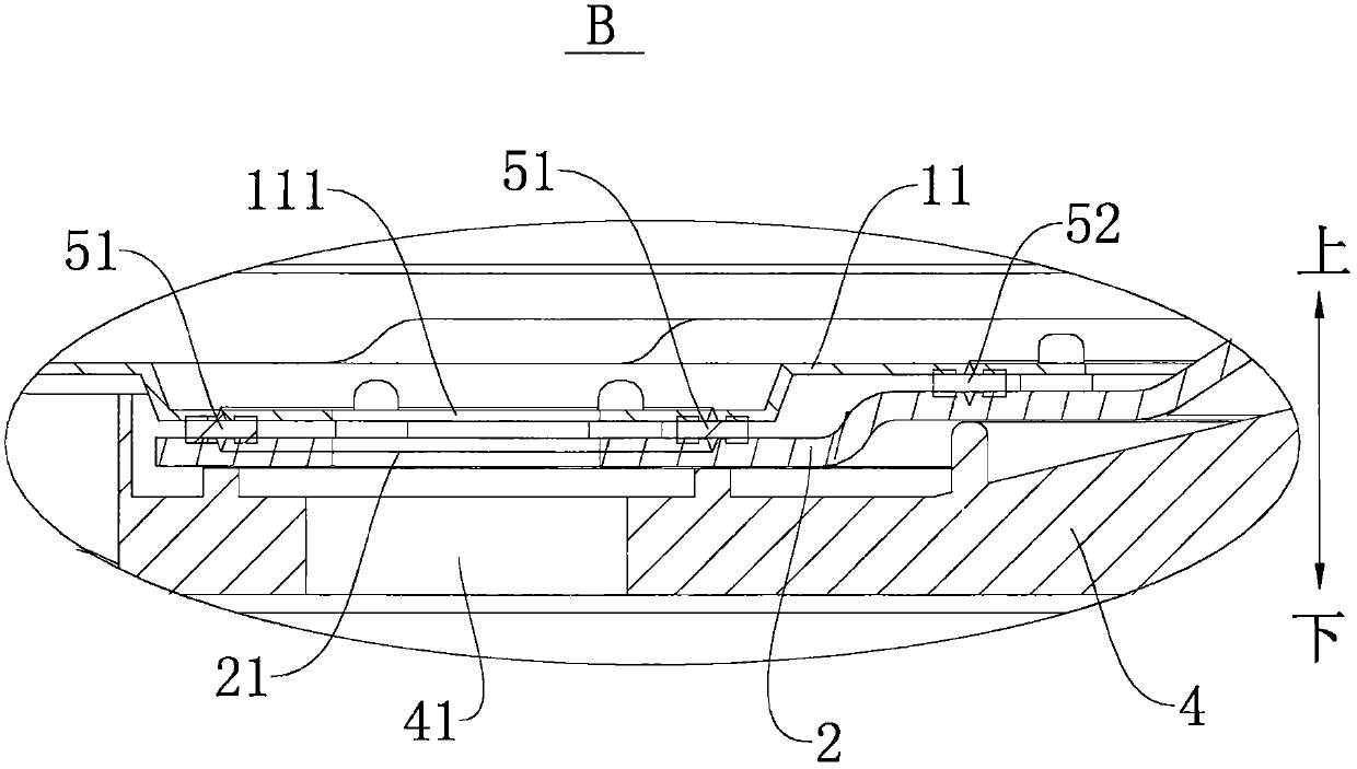
[0093] refer to Figure 1-Figure 5 , the pulsator washing machine 100 comprises: a non-porous inner tub 1, a connection plate 4, a sealing disc 2 and a driving device 3, the connection plate 4 is located below the bottom 11 of the non-porous inner tub 1, and the connection plate 4 is connected to the bottom of the non-porous inner tub 1 11 screw connection, the connecting plate 4 is connected with the driving device 3. The sealing disc 2 is rotatably arranged at the bottom of the non-porous inner barrel 1 between the open position and the closed position, and the sealing disc 2 is located above the connecting disc 4, further, the sealing disc 2 is located under the bottom 11 of the non-porous inner barrel 1 side, located between the barrel bottom 11 of the non-porous inner barrel 1 and the connection plate 4 .
[0094] The driving device 3 includes: a motor 31 and a clutch 32, the clutch 32 has a first output shaft 321 and a second output shaft 322, the first output shaft 321...
Embodiment 2
[0104] Such as Figure 1-Figure 5 As shown, the structure of this embodiment is substantially the same as that of Embodiment 1, wherein the same components use the same reference numerals, and the only difference is that in Embodiment 1, the sealing disc 2 passes through the second limiting portion 22 (limiting convex platform) to embed the first limit pit and the second limit pit of the first limit portion 112 to determine whether it is in the open position and the closed position, while the barrel bottom 11 of the non-porous inner barrel 1 in the second embodiment is not provided with the first limit pit. The limit part 112, and the second limit part 22 is not provided on the sealing disc 2, and the Hall sensor 33 is provided on the driving device 3, and the Hall sensor 33 is used to detect the contact between the sealing disc 2 and the barrel bottom 11 of the non-porous inner barrel 1. The relative rotation angle determines whether the sealing disc 2 is in the open position...
Embodiment 3
[0109] Such as Figure 6-Figure 8 As shown, the structure of the present embodiment is substantially the same as that of the second embodiment, wherein the same components use the same reference numerals, the difference is that the bottom 11 of the non-porous inner barrel 1 in the second embodiment is provided with a drainage hole 111, and The sealing disc 2 is located on the lower side of the barrel bottom 11 of the non-porous inner barrel 1, while the barrel bottom 11 of the non-porous inner barrel 1 in the third embodiment is provided with an opening 113, the connecting plate 4 closes the opening 113, and the sealing disc 2 is located on the connecting plate 4 and located inside the non-porous inner barrel 1. And the radial dimension of the opening 113 of the sealing disc 2 is larger than the radial dimension of the sealing disc 2 .
[0110] A third sealing ring 53 is connected between the periphery of the connection plate 4 and the bottom 11 of the non-porous inner barrel...
PUM
 Abstract
Description
Claims
Application Information
 - R&D
- Intellectual Property
- Life Sciences
- Materials
- Tech Scout
- Unparalleled Data Quality
- Higher Quality Content
- 60% Fewer Hallucinations
Browse by: Latest US Patents, China's latest patents, Technical Efficacy Thesaurus, Application Domain, Technology Topic, Popular Technical Reports.
© 2025 PatSnap. All rights reserved.Legal|Privacy policy|Modern Slavery Act Transparency Statement|Sitemap|About US| Contact US: help@patsnap.com