Binocular vision positioning method and binocular vision positioning device for robots, and storage medium

A binocular vision positioning and robot technology, applied in the field of robot navigation, can solve problems such as closed-loop optimization failure, large pose drift, and inaccurate robot pose estimation

Active Publication Date: 2018-03-13
HANGZHOU JIAZHI TECH CO LTD
View PDF4 Cites 61 Cited by
  • Summary
  • Abstract
  • Description
  • Claims
  • Application Information

AI Technical Summary

Problems solved by technology

However, the existing visual odometry calculation method will make errors due to accumulated errors during long-term operation, and the visual positioning method is easily affected by ambient light and climate change, making it difficult to achieve a stable association with the visual map or prior image, resulting in positioning failure. , which in turn affects the completion of the robot task
There is also a method of using c

Method used


Image

  • Binocular vision positioning method and binocular vision positioning device for robots, and storage medium
  • Binocular vision positioning method and binocular vision positioning device for robots, and storage medium
  • Binocular vision positioning method and binocular vision positioning device for robots, and storage medium

Examples


Embodiment 1

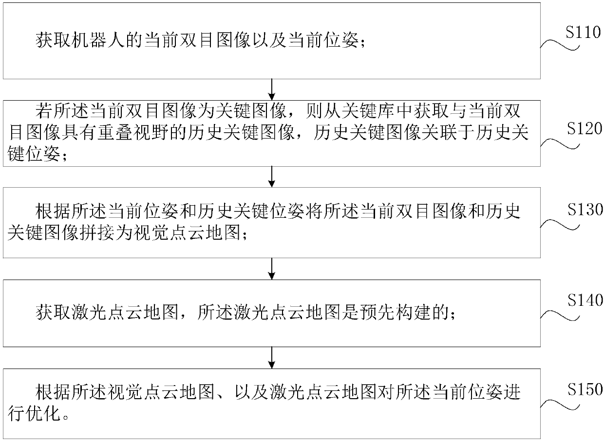
[0061] Such as figure 1 A binocular vision positioning method for a robot, comprising the following steps:

[0062] Step S110, acquiring the current binocular image and the current pose of the robot.

[0063] As a preferred implementation, step S110 acquires the current binocular image and the current pose of the robot, which specifically includes the following sub-steps:

[0064] Step S111, acquiring the current binocular image of the robot, as well as the previous binocular image and previous pose of the robot;

[0065] Step S112, calculating the amount of pose change according to the current binocular image and the previous binocular image;

[0066] Step S113, calculating the current pose of the robot according to the amount of pose change and the previous pose.

[0067] The use of binocular vision to realize the motion estimation of the robot itself has a long research history. Most of the implementation methods are to use the image information of adjacent frames to est...

Embodiment 2

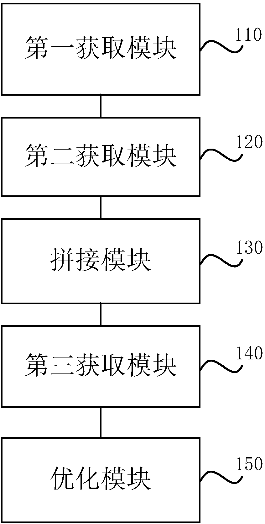
[0115] Such as image 3 The robot binocular vision positioning device shown includes:

[0116] The first acquiring module 110 is used to acquire the current binocular image and the current pose of the robot;

[0117] The second acquisition module 120 is used to obtain a historical key image with an overlapping field of view with the current binocular image from the key library if the current binocular image is a key image, and the historical key image is associated with the historical key pose;

[0118] The splicing module 130 is used for splicing the current binocular image and the historical key image into a visual point cloud map according to the current pose and the historical key pose;

[0119] The third obtaining module 140 is used to obtain the laser point cloud map, and the laser point cloud map is pre-built;

[0120] The optimization module 150 is configured to optimize the current pose according to the visual point cloud map and the laser point cloud map.

[0121]...

Embodiment 3

[0134] Such as Figure 4 An electronic device shown includes a memory 200, a processor 300, and a program stored in the memory 200. The program is configured to be executed by the processor 300. When the processor 300 executes the program, the robot binocular vision positioning described above is realized. method steps.


PUM


Abstract

The invention discloses a binocular vision positioning method and a binocular vision positioning device for robots, and a storage medium. The binocular vision positioning method includes acquiring current binocular images and current positions and posture of the robots; acquiring historical key images from key libraries if the current binocular images are key images; splicing the current binocularimages and the historical key images according to the current positions and posture and historical key positions and posture to obtain vision point cloud maps; acquiring preliminarily built laser point cloud maps; optimizing the current positions and posture according to the vision point cloud maps and the laser point cloud maps. The historical key images acquired from the key libraries and the current binocular images have overlapped visual fields, and the historical key images are related to the historical key positions and posture. The binocular vision positioning method, the binocular vision positioning device and the storage medium have the advantages that position and posture estimated values are optimized by the aid of the preliminarily built laser point cloud maps at moments corresponding to key frames, and accordingly position and posture estimation cumulative errors can be continuously corrected in long-term robot operation procedures; information of the accurate laser pointcloud maps is imported in optimization procedures, and accordingly the binocular vision positioning method and the binocular vision positioning device are high in positioning accuracy.

Description

technical field [0001] The invention relates to robot navigation technology, in particular to a robot binocular vision positioning method, device and storage medium. Background technique [0002] At present, more and more different types of robots appear in all aspects of production and life. For warehousing logistics, inspection and monitoring and other fields, the work requires robots to be able to achieve long-term stable operation in a relatively fixed environment, and to achieve accurate self-positioning. At this stage, the positioning method based on 3D laser radar and prior laser map can meet this demand, but the cost of 3D laser is relatively high, which is not suitable for the widespread application of robots. The cost of visual sensors is low, and the amount of information obtained is large. If the visual sensor is used to realize this function, the production cost can be reduced to a large extent. However, the existing visual odometry calculation method will mak...

Claims


Application Information

Patent Timeline
IPC IPC(8): G01C21/20G01C11/02G01C11/04
CPCG01C11/02G01C11/04G01C21/20
Inventor 王越丁夏清
Owner HANGZHOU JIAZHI TECH CO LTD
Why Eureka
Try Eureka