
Failure detection device of power converter and vehicle

一种电力转换装置、故障探测的技术,应用在用电装置、车辆部件、电动汽车等方向,能够解决温度变化等问题

Active Publication Date: 2018-03-13
HONDA MOTOR CO LTD
View PDF5 Cites 6 Cited by
  • Summary
  • Abstract
  • Description
  • Claims
  • Application Information

AI Technical Summary

Problems solved by technology

Also, large currents flow in these power semiconductor elements, so their temperatures vary greatly

Method used


Image

  • Failure detection device of power converter and vehicle
  • Failure detection device of power converter and vehicle
  • Failure detection device of power converter and vehicle

Examples


no. 1 Embodiment approach >

[0064] Hereinafter, a first embodiment of the present invention will be described with reference to the drawings.

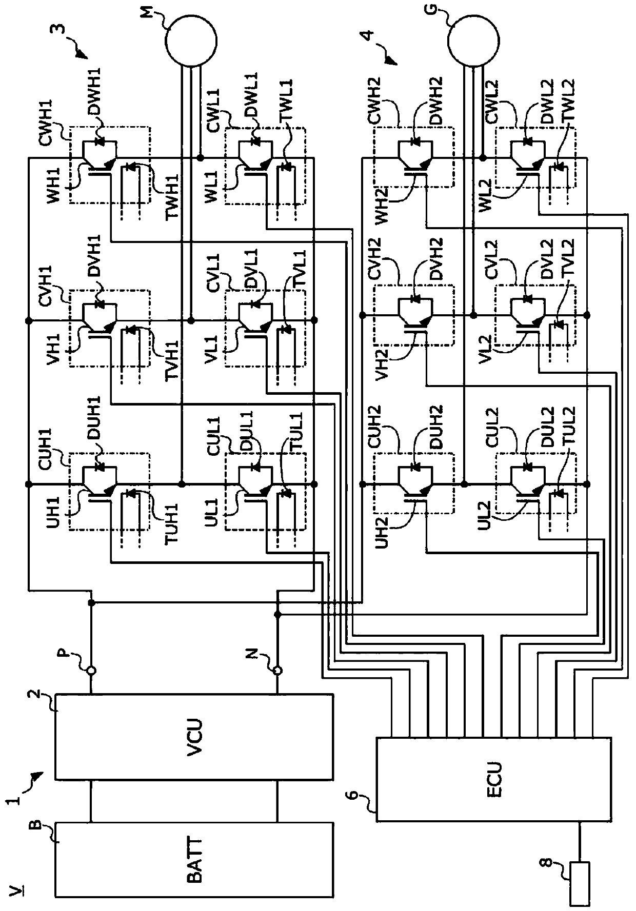
[0065] figure 1 It is a diagram showing the circuit configuration of a vehicle V and a power control unit (hereinafter referred to as "PCU") 1 mounted on the vehicle V according to the present embodiment.

[0066] The vehicle V is a so-called hybrid vehicle and includes: an engine (not shown) that drives driving wheels (not shown); a generator G that is an electric motor that is driven by the output of the engine; a battery B that is a DC power supply , to charge through the output of the generator G; the traction motor (traction motor) (hereinafter referred to as "motor") M as an electric motor, uses the electric power of the battery B to drive the drive wheels; PCU 1, controls the battery B, power generation The receiving and receiving of electric power between the engine G and the motor M; and the warning lamp 8 as a notification means, which is lit when the ...

no. 2 Embodiment approach >

[0106] Hereinafter, a vehicle and its power control unit according to a second embodiment of the present invention will be described with reference to the drawings. In addition, in the following description of the second embodiment, the same components as those of the vehicle of the first embodiment are given the same reference numerals, and their descriptions are omitted.

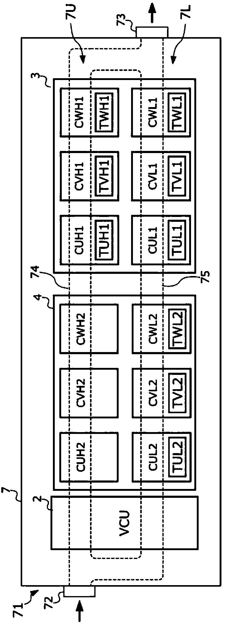
[0107] In the first embodiment, as referring to figure 2 As described above, the case where the difference between the refrigerant flow rate of the high arm side refrigerant flow channel 74 and the refrigerant flow rate of the low arm side refrigerant flow channel 75 is equal to or greater than the predetermined flow rate has been described. In this embodiment, a case where the difference between the refrigerant flow rate of the high arm side refrigerant flow passage 74 and the refrigerant flow rate of the low arm side refrigerant flow passage 75 is within a predetermined flow rate will be described. At ...


PUM


Abstract

A power converter which can prevent an erroneous detection even when a flow rate of a refrigerant is low and a vehicle having the power converter mounted therein are provided. A first inverter circuit(3) including: an element group constituted by six transistors (UH1, UL1, VH1, VL1, WH1, WL1); six diode temperature sensors (TUH1, TUL1, TVH1, TVL1, TWH1, TWL1) at least one of which is provided foreach transistor to detect a temperature of the transistor; and a high arm-side refrigerant flow passage (74) and a low arm-side refrigerant flow passage (75) in which a refrigerant for cooling the transistors flows is provided. In a failure detection device of the first inverter circuit (3), a failure determination member selects two diode temperature sensors among the plurality of diode temperature sensors, which detect temperatures of two adjacent transistors, as an adjacent sensor pair, and determines a failure of any one of the plurality of diode temperature sensors using detection valuesof the adjacent sensor pair.

Description

technical field [0001] The present invention relates to a fault detection device for a power conversion device and a vehicle equipped with the device. In more detail, the present invention relates to a failure detection device for detecting a failure of a temperature detection part that monitors the temperature of a switching element mounted in a power conversion device, and a vehicle equipped with the device. detection. Background technique [0002] In recent years, vehicles that run using a motor (motor), such as hybrid vehicles, fuel cell vehicles, and electric vehicles, are advancing in popularity. Such a motor vehicle is equipped with a converter device that boosts the voltage supplied from the battery, converts the DC voltage boosted by the converter device into an AC voltage, and supplies it to the Motor power conversion devices, etc. Also, these converter devices, power conversion devices, and the like are accommodated in a case formed with a water jacket for cool...

Claims


Application Information

Patent Timeline
Patent Type & Authority Applications(China)
IPC IPC(8): G01K13/02G01K15/00
CPCG01K13/02G01K15/007G01K13/026B60L3/003B60L2240/36
Inventor 笠置宏辅福井二郎野村拓哉松本智代
Owner HONDA MOTOR CO LTD
Learn More