
Carrying device auxiliary system capable of achieving big data collection management

An auxiliary system and big data technology, applied in general control systems, control/regulation systems, instruments, etc., can solve problems such as safety liability accidents, achieve stable operation, avoid mistakes in human judgment, and low design and use costs. Effect

Inactive Publication Date: 2018-03-13
成都量之星科技有限公司
View PDF2 Cites 1 Cited by
  • Summary
  • Abstract
  • Description
  • Claims
  • Application Information

AI Technical Summary

Problems solved by technology

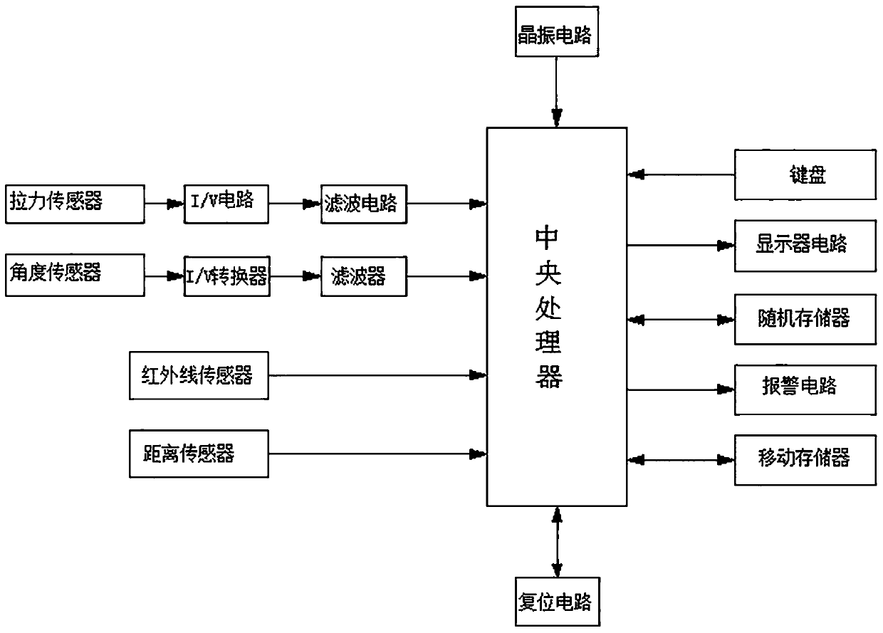
[0010] The purpose of the present invention is to provide an auxiliary system for carrying equipment that can realize large data collection and management, use sensor technology to convert non-electric power (pull force, angle, etc.) to electric power, and then adjust according to the collected sensor information The information is adjusted for displacement, so that the object can be displaced safely and quickly, so as to solve the shortcomings of the existing technology that requires manual viewing and is not punctual, and is prone to safety liability accidents; when converting the signal output by the angle sensor At the same time, the I / V converter designed based on the integrated op amp converts the current to the voltage signal, and converts the current signal of about 4 ~ 20mA into a voltage signal of 0 ~ 2.5V suitable for the central processing unit, and then transmits it after filtering To the AD circuit of the central processing unit for subsequent processing, the whole system, especially the angle sensor circuit is simple to design the circuit to achieve the required functions, with the advantages of low design cost and use cost, but stable operation

Method used


Image

  • Carrying device auxiliary system capable of achieving big data collection management
  • Carrying device auxiliary system capable of achieving big data collection management

Examples


Embodiment 1

[0035] An auxiliary system for carrying equipment that can realize big data collection and management, using sensor technology to convert non-electric power (pull force, angle, etc.) It can safely and quickly displace the object, so as to solve the shortcomings of the existing technology that need to be manually viewed and the point of view is not punctual, which is prone to safety liability accidents; when converting the signal output by the angle sensor, through the integrated operation The I / V converter designed for the amplifier converts the current to the voltage signal, converts the current signal of about 4-20mA into a voltage signal of 0-2.5V suitable for the central processing unit, and then sends it to the AD of the central processing unit after filtering. Subsequent processing is carried out in the circuit, and the whole system, especially the angle sensor circuit, is simple to design the circuit to realize the required functions. It has the advantages of low design ...

Embodiment 2

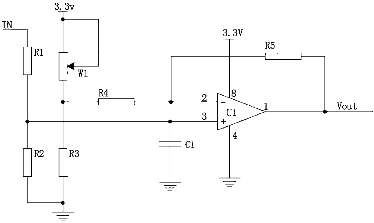
[0039] This embodiment is further optimized on the basis of the above embodiments, such as figure 1 , figure 2 As shown, further in order to better realize the present invention, the following arrangement structure is adopted in particular: the inverting input circuit includes resistor R1 and resistor R2, the non-inverting input circuit includes potentiometer W1, resistor R4 and resistor R3, and the resistor R1 and resistor R2 are connected in series with each other and the resistor R1 and resistor R2 connected in series are connected between the output terminal of the angle sensor and the ground, and the non-inverting input terminal of the integrated operational amplifier U1 is connected to the common terminal of the resistor R1 and the resistor R2; the potentiometer W1 and resistor R3 are connected in series with each other and connected between the power supply of the angle sensor circuit and the ground. The common terminal of the potentiometer W1 and the resistor R3 is co...

Embodiment 3

[0041] This embodiment is further optimized on the basis of any of the above embodiments, such as figure 1 , figure 2 As shown, further in order to better realize the present invention, the following arrangement structure is adopted in particular: a fixed end of the potentiometer W1 is connected to the power supply of the angle sensor circuit, and the power supply of the angle sensor circuit adopts 3.3V direct current , the integrated operational amplifier U1 adopts LMV358, and the angle sensor adopts BROSA-0802 angle sensor.

[0042] When designing and using, the angle sensor BROSA-0802 collects the elevation angle signal of the main arm (real-time detection value), and then forms a current signal of about 4-20mA, and converts it into a 0-2.5V suitable for the central processing unit through the I / V converter The voltage signal is finally sent to the filter for filtering, and then sent to the central processing unit. The central processing unit sends an adjustment signal to...


PUM


Abstract

The present invention discloses a carrying device auxiliary system capable of achieving big data collection management. The carrying device auxiliary system comprises a processor system, a tension sensor circuit and an angle sensor circuit. The processor system comprises a central processing unit and a processor system circuit; the angle sensor circuit is internally provided with an angle sensor,an I / V converter and a filter; the I / V converter comprises an in-phase input circuit, an inverted input circuit and an amplification circuit; an output end of the angle sensor is connected with an in-phase input end of an integration operational amplifier U1 through the in-phase input circuit, the inverted input circuit is connected at an inverted input end of the integration operational amplifierU1, the in-phase input end of the integration operational amplifier U1 is earthed through a capacitor C1, a resistor R5 is connected between the inverted input end and an output end of the integration operational amplifier U1, and the output end of the integration operational amplifier U1 is connected with the filter. The angle sensor circuit employs a simple design circuit to achieve required functions, and is low in cost and stable in operation.

Description

technical field [0001] The present invention relates to the fields of sensor technology, displacement equipment technology, current-voltage conversion technology, etc., specifically, it is a carrier equipment auxiliary system capable of realizing large data collection and management. Background technique [0002] A sensor is a device or device that can sense a specified measured value and convert it into a usable output signal according to certain rules. my country's national standard (GB7665-2005) defines a sensor as: "a device or device that can sense what is being measured and convert it into a usable output signal according to certain rules." [0003] As an important means of information acquisition, sensors, together with communication technology and computer technology, constitute the three pillars of information technology. [0004] Function: Use physical effects, chemical effects, and biological effects to convert the measured physical quantities, chemical quantitie...

Claims


Application Information

Patent Timeline
Patent Type & Authority Applications(China)
IPC IPC(8): G05B19/042G01D21/02
CPCG05B19/042G01D21/02
Inventor 李永量
Owner 成都量之星科技有限公司
Learn More