Fixing heat dissipating unit and electronic device having fixing heat dissipating unit

a technology of fixing heat dissipating unit and electronic device, which is applied in the direction of lighting and heating apparatus, electrical equipment casings/cabinets/drawers, instruments, etc., can solve the problems of increasing design cost, fan or heat pipe taking a lot of space in the electronic device, and malfunction of electronic devices, so as to improve heat dissipation efficiency and increase heat dissipation area , the effect of reducing design cos

Inactive Publication Date: 2010-05-04
ARCADYAN
View PDF11 Cites 2 Cited by
  • Summary
  • Abstract
  • Description
  • Claims
  • Application Information

AI Technical Summary

Benefits of technology

[0011]As described above, with the integrated functions of holding and heat dissipating, the fixing heat dissipating unit and the electronic device having the fixing heat dissipating unit according to the present invention transmit the heat energy generated by the heat source through the heat conducting element to the entire fixing heat dissipating unit so as to enhance the heat dissipating efficiency by increasing the heat dissipating area. Compared to the prior art, the fixing heat dissipating unit and the electronic device of the present invention can match the positions of different substrates to provide the functions of heat dissipating and holding. Therefore, this can lower the design cost, reduce the testing time and effectively increase the reliability of the electronic product.

Problems solved by technology

The accumulating heat energy may, however, easily overheat the electronic device and hence lead to the malfunction of the electronic device.
Nevertheless, the fan or the heat pipe takes a lot of space in the electronic device; and as for the fan, the heat flow is also another factor to be considered while designing.
Hence other than the material cost, the design cost will as well be increased.
Additionally, the shaking occurred while moving the electronic device may damage the elements in the electronic device.
The above heat dissipating element and fixing element are usually separate elements, so the design cost or the testing time cannot be effectively controlled.

Method used


Image

  • Fixing heat dissipating unit and electronic device having fixing heat dissipating unit
  • Fixing heat dissipating unit and electronic device having fixing heat dissipating unit
  • Fixing heat dissipating unit and electronic device having fixing heat dissipating unit

Examples


Embodiment Construction

[0017]The present invention will be apparent from the following detailed description, which proceeds with reference to the accompanying drawings, wherein the same references relate to the same elements.

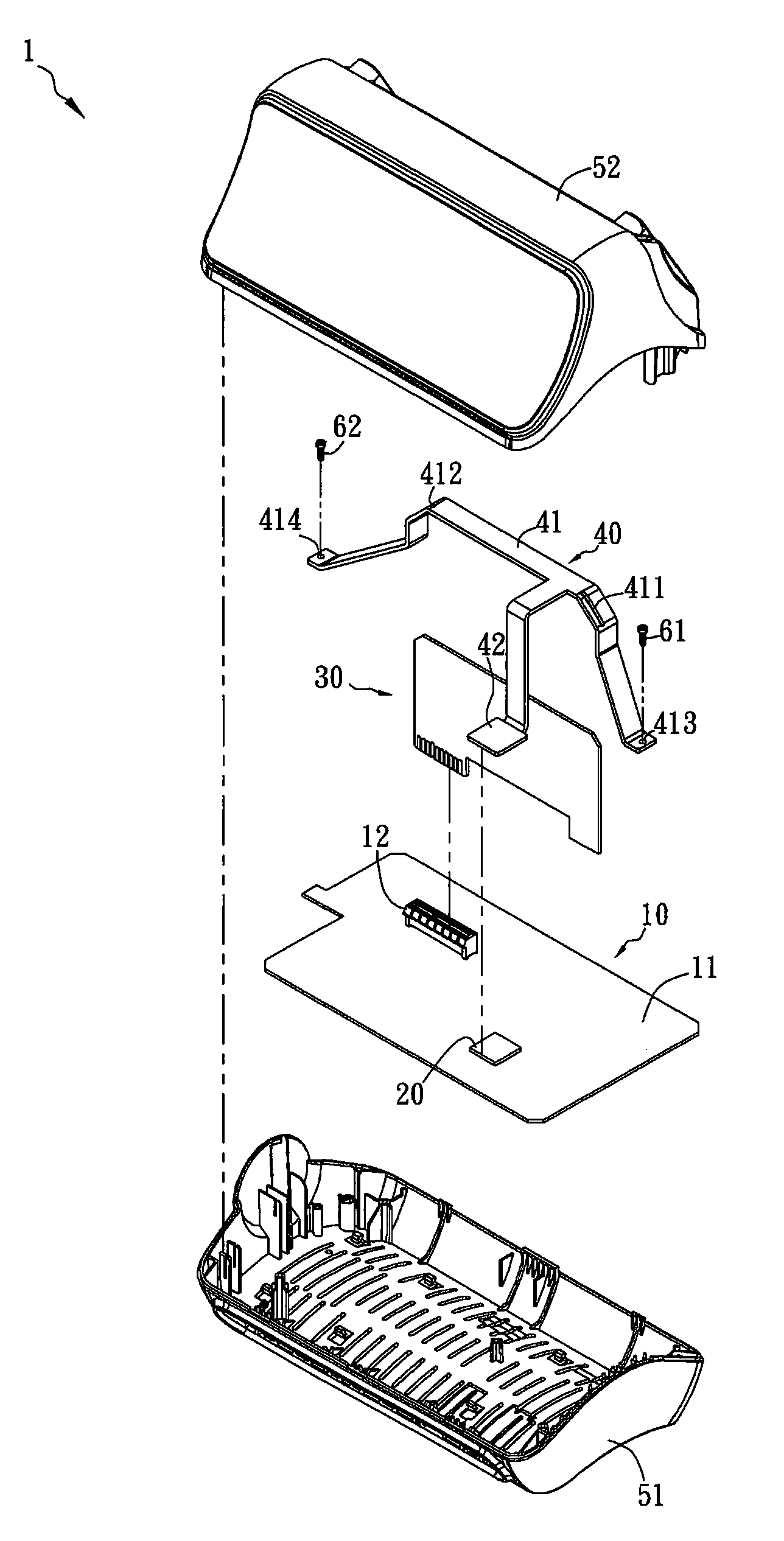
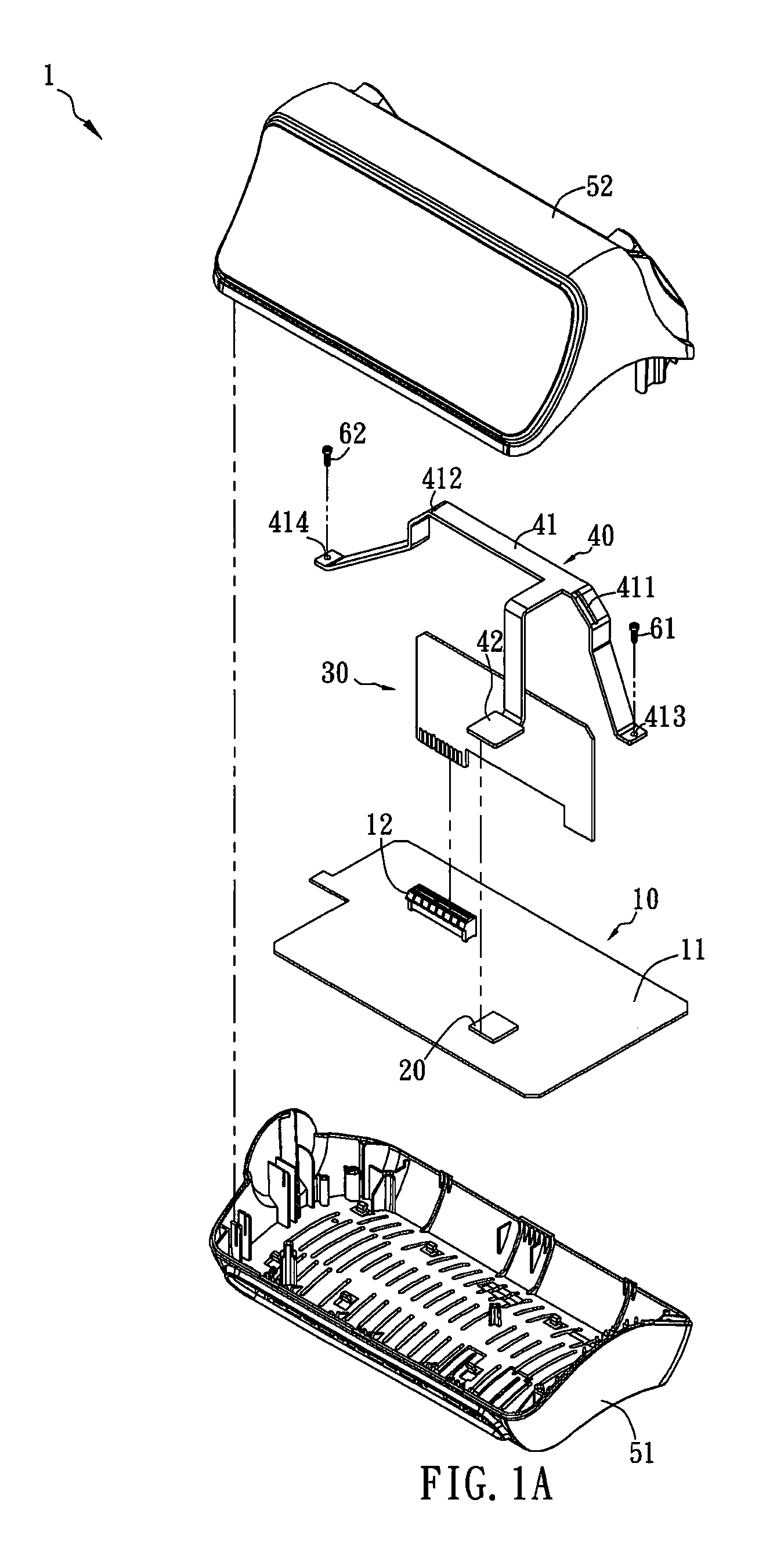
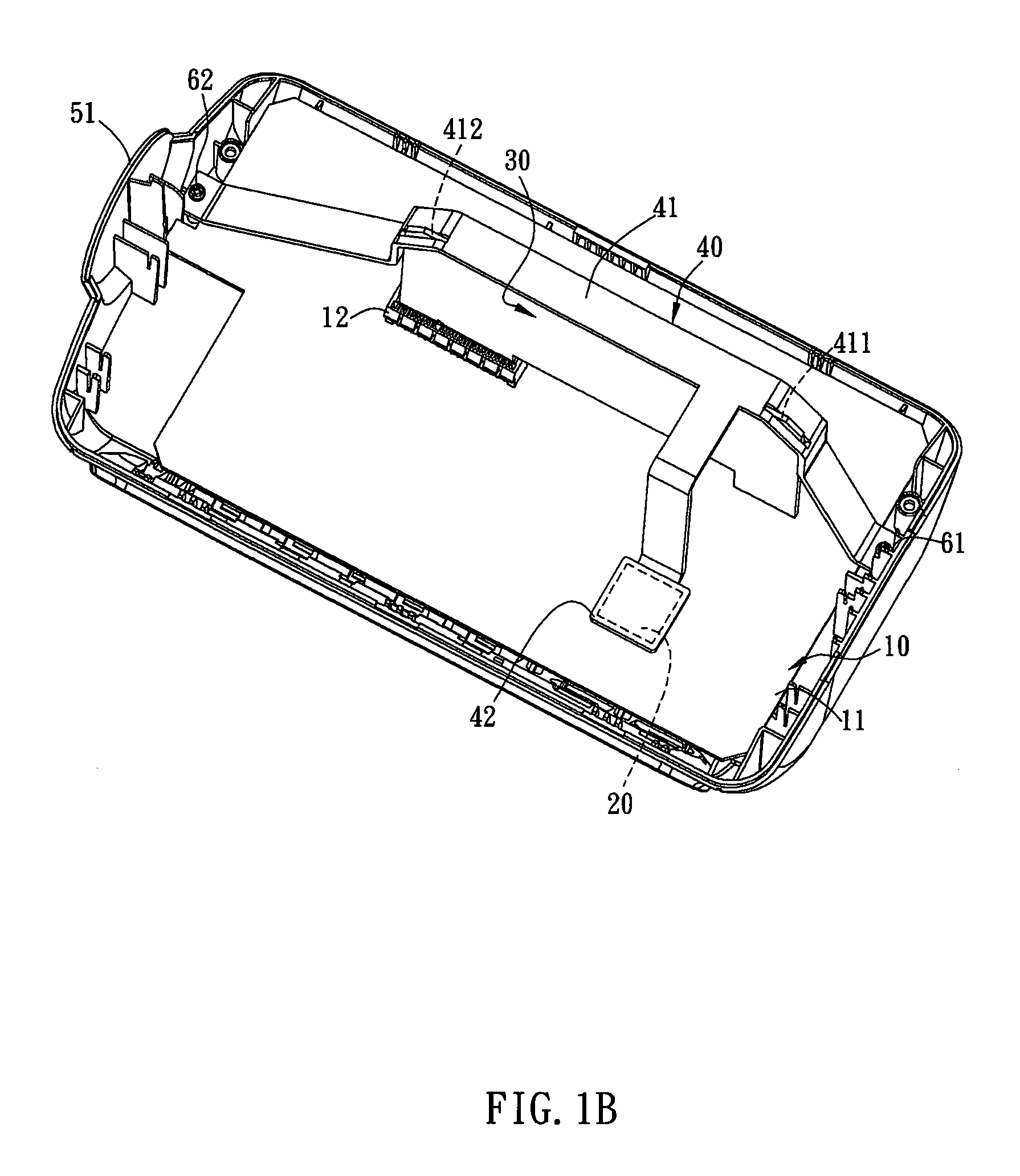
[0018]FIG. 1A is an exploded view of an electronic device according to a preferred embodiment of the present invention. FIG. 1B is an assembled view of a part of the electronic device in FIG. 1A.

[0019]Referring to FIGS. 1A and 1B, an electronic device 1 includes a first substrate 10, a heat source 20, a second substrate 30, and a fixing heat dissipating unit 40. The electronic device 1 may be a desktop, a laptop, an internet communication device, or a display device. In the embodiment, the electronic device 1 is an internet communication device applied to, for example, ADSL or VDSL.

[0020]The heat source 20 is disposed on a surface 11 of the first substrate 10. In the embodiment, the heat source 20 is, for example, a chip or an active electronic element such as a transistor, which usua...


PUM


Abstract

A fixing heat dissipating unit that is disposed in an electronic device is connected to a substrate and a heat source. The fixing heat dissipating unit includes a fixing element and a heat conducting element. The fixing element is connected to the substrate to hold the substrate in the electronic device. The heat conducting element is respectively connected to the heat source and the fixing element. The heat source is a part of the electronic device and the fixing element is integrated with the heat conducting element as a single component. An electronic device having the fixing heat dissipating unit is also disclosed.

Description

CROSS REFERENCE TO RELATED APPLICATIONS[0001]This Non-provisional application claims priority under 35 U.S.C. §119(a) on Patent Application No(s). 097130159 filed in Taiwan, Republic of China on Aug. 7, 2008, the entire contents of which are hereby incorporated by reference.BACKGROUND OF THE INVENTION[0002]1. Field of Invention[0003]The present invention relates to a fixing heat dissipating unit with integrated functions of holding and heat dissipating, and an electronic device having the fixing heat dissipating unit.[0004]2. Related Art[0005]As the electronic devices are operating, the elements inside, such as the chips, usually generate heat energy. The accumulating heat energy may, however, easily overheat the electronic device and hence lead to the malfunction of the electronic device. Thus, the electronic device usually has a heat dissipating element, such as a fan, a metal heat dissipation sheet, a ceramic heat dissipation sheet, or a heat pipe, for heat dissipation. Neverthel...

Claims


Application Information

Patent Timeline
Patent Type & Authority Patents(United States)
IPC IPC(8): H05K7/20H05K7/02
CPCH05K7/2049H05K7/20445H05K1/141H05K3/301H05K3/366
Inventor CHEN, LIANG-WEI
Owner ARCADYAN
Why Eureka
Try Eureka