Displacement system capable of smoothly running based on network data safety management design
A technology of network data and safety management, applied in the field of displacement devices with stable operation based on network data safety management design, can solve problems such as safety liability accidents, achieve stable operation, avoid safety liability accidents, and achieve low design and use costs
- Summary
- Abstract
- Description
- Claims
- Application Information
AI Technical Summary
Problems solved by technology
Method used
Image
Examples
Embodiment 1
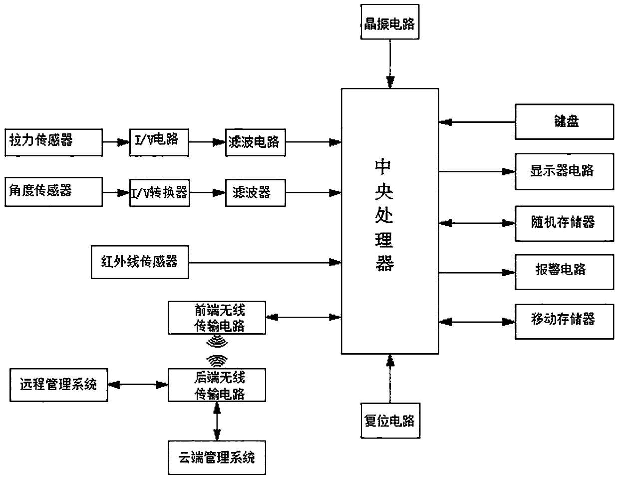
[0040] A displacement device with stable operation and design based on network data security management, which uses sensor technology to convert non-electric power (pull force, angle, etc.) It can safely and quickly displace the object, so as to solve the shortcomings of the existing technology that need to be manually watched and the watch is not punctual, and it is easy to cause safety liability accidents; when converting the signal output by the tension sensor, through integrated operation The I / V circuit designed for the amplifier converts the current to the voltage signal, converts the current signal of about 4 ~ 20mA into a voltage signal of 0 ~ 2.5V suitable for the central processing unit, and then sends it to the central processing unit after being filtered by the filter circuit. Follow-up processing is carried out in any AD circuit; the whole system, especially the tension sensor circuit, adopts a design circuit with a second-order low-pass filter function to achieve ...
Embodiment 2
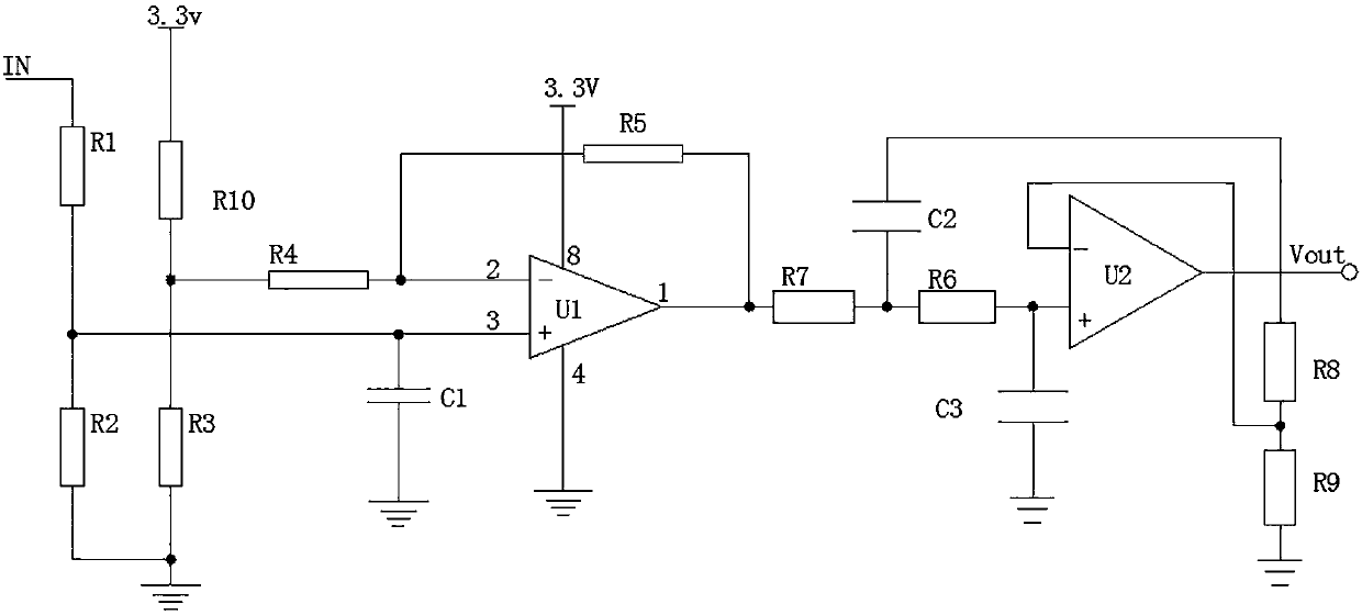
[0044] This embodiment is further optimized on the basis of the above embodiments, such as figure 1 , figure 2 As shown, further in order to better realize the present invention, the following setting structure is particularly adopted: an integrated operational amplifier U1, a capacitor C1 and a resistor R5 are arranged in the first-stage amplifying circuit, and the non-inverting input terminal of the integrated operational amplifier U1 Connect the non-inverting input circuit, the inverting input terminal of the integrated operational amplifier U1 is connected to the inverting input circuit, and the non-inverting input terminal of the integrated operational amplifier U1 is grounded through the capacitor C1, and the resistor R5 is connected between the inverting input terminal and the output of the integrated operational amplifier U1 between the terminals; on the second-stage amplifying circuit, resistors R7, resistor R6, resistor R8, resistor R9, capacitor C2, capacitor C3 an...
Embodiment 3
[0046] This embodiment is further optimized on the basis of any of the above embodiments, such as figure 1 , figure 2 As shown, further in order to better realize the present invention, the following arrangement structure is adopted in particular: the inverting input circuit includes resistor R1 and resistor R2, the non-inverting input circuit includes resistor R10, resistor R4 and resistor R3, resistor R1 The resistor R1 and the resistor R2 connected in series with the resistor R2 are connected between the output terminal of the tension sensor and the ground, and the non-inverting input terminal of the integrated operational amplifier U1 is connected to the common terminal of the resistor R1 and the resistor R2; the resistor R10 and Resistors R3 are connected in series with each other and between the power supply of the tension sensor circuit and the ground, the common terminal of resistor R10 and resistor R3 is connected to the inverting input terminal of the integrated ope...
PUM
 Abstract
Description
Claims
Application Information
 - R&D
- Intellectual Property
- Life Sciences
- Materials
- Tech Scout
- Unparalleled Data Quality
- Higher Quality Content
- 60% Fewer Hallucinations
Browse by: Latest US Patents, China's latest patents, Technical Efficacy Thesaurus, Application Domain, Technology Topic, Popular Technical Reports.
© 2025 PatSnap. All rights reserved.Legal|Privacy policy|Modern Slavery Act Transparency Statement|Sitemap|About US| Contact US: help@patsnap.com


