
High-efficiency 2.4GHz single-mode antenna
A high-efficiency, high-efficiency antenna technology, applied to antennas, antenna parts, antenna supports/mounting devices, etc., can solve problems such as poor redundancy, high height, and complicated antenna installation, and achieve good production consistency, convenient use, and The effect of simple structure
Patent Information
- Authority / Receiving Office
- CN · China
- Current Assignee / Owner
- Publication Date
- 2018-03-13
Smart Images
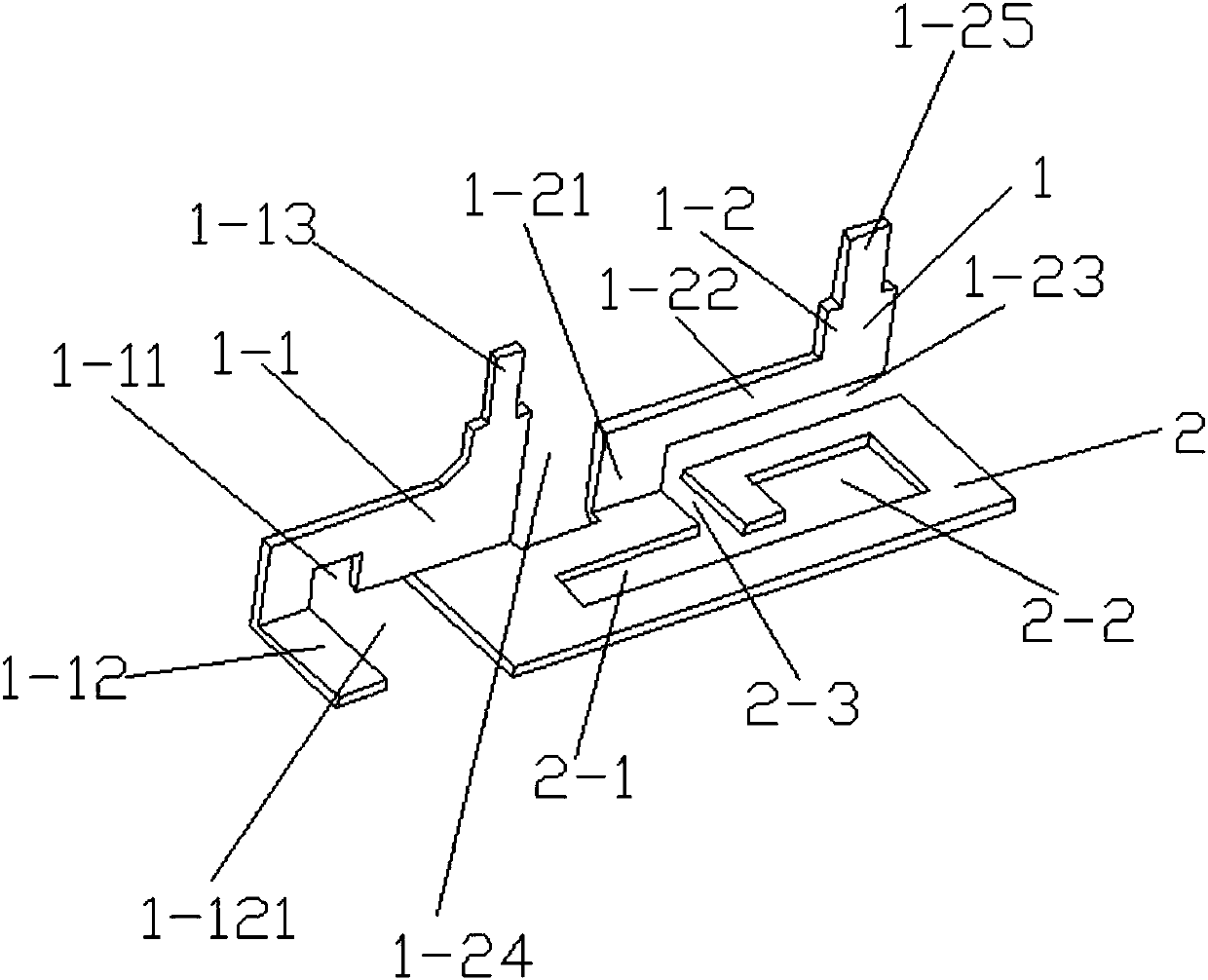
Figure 1 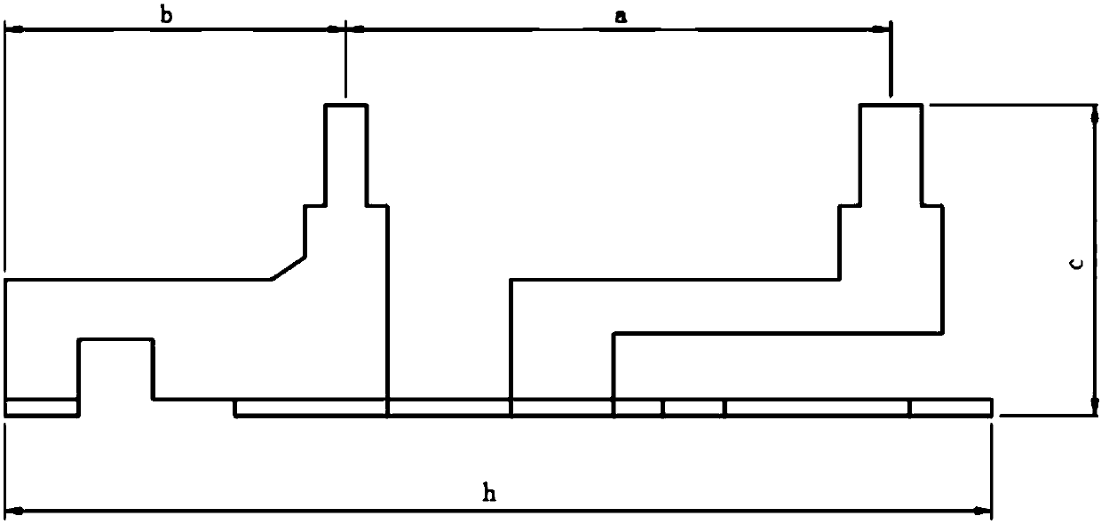
Figure 2 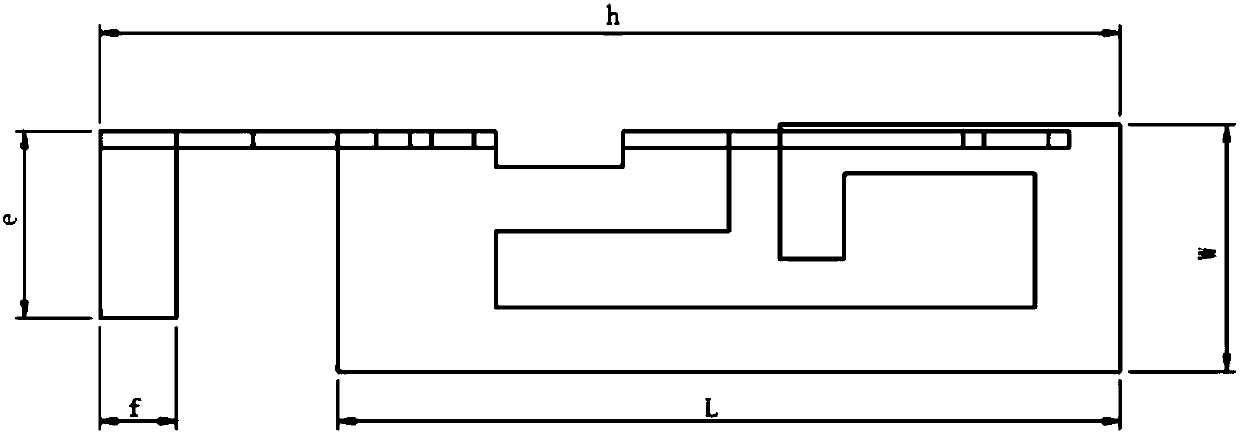
Figure 3
Abstract
Description
technical field
[0001] The invention relates to an antenna, in particular to a 2.4GHz high-efficiency single-mode antenna. Background technique
[0002] Common 2.4GHz antennas on the market are complex to install, low in emission efficiency, large in size, and high in height, which cannot meet the needs of miniaturized products. At the same time, common antennas have poor consistency in mass production, poor redundancy, and high precision requirements, which cannot meet mass industrial production. production capacity requirements, and most of them have launch dead ends. Contents of the invention
[0003] In order to solve the above problems, the present invention provides a 2.4GHz high-efficiency single-mode antenna. The present invention is simple in structure and easy to use. The high efficiency of wireless signal transmission is as high as 75%-80%. The precision of the integrally formed antenna is as high as 0.03mm, and the production consistency Good; error redundancy...
Examples
Embodiment 1
[0015] Embodiment 1: as Figure 1-4 As shown, this embodiment provides a 2.4GHz high-efficiency single-mode antenna, including a circuit board 2 integrally formed with the antenna 1, and the circuit board 2 is provided with a first rectangular slot 2-1, a second rectangular slot 2- 2. The third rectangular groove 2-3, the first rectangular groove 2-1 is arranged on the left side of the circuit board 2, and the second rectangular groove 2-2 is arranged on the right side of the circuit board 2 and the first rectangular groove 2-2. 1, the third rectangular slot 2-3 is set in the middle of the circuit board 2 and communicates with the first rectangular slot 2-1, the antenna 1 includes a left antenna group 1-1, a right antenna group 1-2, and the left antenna group 1-2. The antenna group 1-1 is vertically arranged on the left side of the circuit board 2, and the left antenna group 1-1 is provided with a U-shaped slot 1-11, and the left side of the U-shaped slot 1-11 is provided with...