Seedling tray conveying mechanism used on green Chinese onion transplanter

A seedling tray conveying and transplanting machine technology, applied in the direction of transplanting machinery, application, planting methods, etc., can solve the problems of complexity, huge machinery, unfavorable operation, etc., and achieve simple conveying mechanism, reduce complex structure, and occupy a small space Effect

Pending Publication Date: 2018-03-16
ZHEJIANG RIFA TEXTILE MASCH CO LTD
View PDF10 Cites 0 Cited by
  • Summary
  • Abstract
  • Description
  • Claims
  • Application Information

AI Technical Summary

Problems solved by technology

[0002] It is known to have a transplanting machine applied to green onion transplanting. Compared with manual transplanting, mechanical transplanting reduces labor intensity and improves work efficiency, but the seedling throwing process of existing green onion transplanting machines is all completed manually, while manual The operating speed is limited, resulting in the operating efficiency of the existing green onion transplanting machine not reaching the desired efficiency, which affects the popularization and application of the green onion transplanting machine
[0003] In addition, the mechanism of agricultural machinery is too complicated, which makes the whole machine huge, which is not conducive to operation and other problems; it cannot complete the automatic lowering when transplanting green onions at the same time, the automatic lowering is locked, the seedling tray moves according to the trajectory, and the seedling tray completes a lowering After the machine automatically jumps into the idling state and other continuous problems

Method used


Image

  • Seedling tray conveying mechanism used on green Chinese onion transplanter
  • Seedling tray conveying mechanism used on green Chinese onion transplanter
  • Seedling tray conveying mechanism used on green Chinese onion transplanter

Examples


Embodiment 1

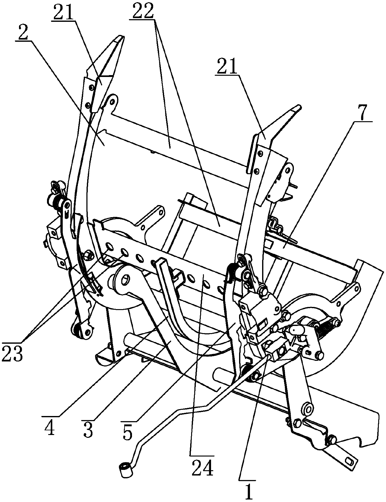
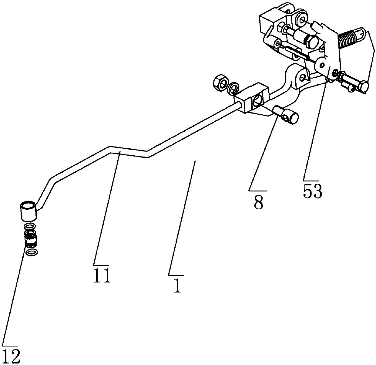
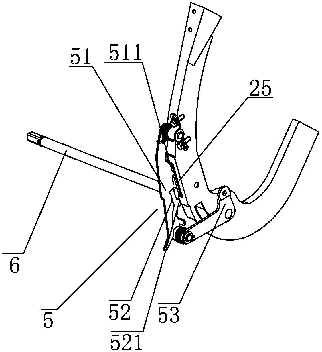
[0014] Embodiment one: see Figure 1-3 As shown, a seedling tray conveying mechanism applied to a green onion transplanting machine includes a seedling tray upper conveying frame 2 and a seedling tray lower conveying frame 3 that are mutually matched and connected through a pull rod assembly 1 and forms a seedling tray passing through a track 4; The conveying frame 2 on the seedling tray is provided with a connecting rod assembly 5 near the side of the pull rod assembly 1. The connecting rod assembly 5 includes an upper connecting rod 51 that is movably installed on the conveying frame 2 on the seedling tray, and moves synchronously with the pull rod assembly 1 through the transmission rod 53. The lower connecting rod 52, the upper connecting rod 51 and the lower connecting rod 52 are connected with each other.

[0015] The conveying frame 2 on the seedling tray includes two symmetrically arranged U-shaped vertical frames 21 and several horizontal frames 22; wherein, the sever...

Embodiment 2

[0016] Embodiment two: see Figure 1-3 As shown, a seedling tray conveying mechanism applied to a green onion transplanting machine includes a seedling tray upper conveying frame 2 and a seedling tray lower conveying frame 3 that are mutually matched and connected through a pull rod assembly 1 and forms a seedling tray passing through a track 4; The conveying frame 2 on the seedling tray is provided with a connecting rod assembly 5 near the side of the pull rod assembly 1. The connecting rod assembly 5 includes an upper connecting rod 51 that is movably installed on the conveying frame 2 on the seedling tray, and moves synchronously with the pull rod assembly 1 through the transmission rod 53. The lower connecting rod 52, the upper connecting rod 51 and the lower connecting rod 52 are connected with each other.

[0017] The lower conveying frame 3 of the seedling tray is located at the bottom of the upper conveying frame 2 of the seedling tray, and the lower conveying frame 3 ...

Embodiment 3

[0018] Embodiment three: see Figure 1-3 As shown, a seedling tray conveying mechanism applied to a green onion transplanting machine includes a seedling tray upper conveying frame 2 and a seedling tray lower conveying frame 3 that are mutually matched and connected through a pull rod assembly 1 and forms a seedling tray passing through a track 4; The conveying frame 2 on the seedling tray is provided with a connecting rod assembly 5 near the side of the pull rod assembly 1. The connecting rod assembly 5 includes an upper connecting rod 51 that is movably installed on the conveying frame 2 on the seedling tray, and moves synchronously with the pull rod assembly 1 through the transmission rod 53. The lower connecting rod 52, the upper connecting rod 51 and the lower connecting rod 52 are connected with each other. The seedling dish that is positioned at the conveying rack 3 under the seedling dish is provided with an automatic neutral gear 7 at the exit of the track 4 .

[001...


PUM


Abstract

The invention belongs to the field of agricultural mechanical equipment, and specifically relates to a seedling tray conveying mechanism used on a green Chinese onion transplanter. The seedling tray conveying mechanism comprises an upper seedling tray conveying rack and a lower seedling tray conveying rack which are connected with each other cooperatively through a pull rod assembly, and a seedling tray rail is formed; a connecting rod assembly is arranged on the side, close to the pull rod assembly, of the upper seedling tray conveying rack, the connecting rod assembly comprises an upper connecting rod movably mounted on the upper seedling tray conveying rack and a lower connecting rod in synchronous movement with the pull rod assembly through a conveying rod, and the upper connecting rodand the lower connecting rod are connected with each other cooperatively. According to the seedling tray conveying mechanism, automatic feeding and automatic feeding locking during green Chinese onion transplanting can be completed simultaneously, seedling trays are moved according to a track, and the machine automatically jumps in an idle state after one-time feeding of the seedling trays is completed.

Description

technical field [0001] The invention belongs to the field of agricultural machinery and equipment, and in particular relates to a seedling tray conveying mechanism applied to a green onion transplanting machine. Background technique [0002] It is known to have a transplanting machine applied to green onion transplanting. Compared with manual transplanting, mechanical transplanting reduces labor intensity and improves work efficiency, but the seedling throwing process of existing green onion transplanting machines is all completed manually, while manual Operating speed is limited, causing the operating efficiency of the existing green onion transplanting machine to be less than the desired efficiency, which affects the popularization and application of the green onion transplanting machine. [0003] In addition, the mechanism of agricultural machinery is too complicated, which makes the whole machine huge, which is not conducive to operation and other problems; it cannot com...

Claims


Application Information

Patent Timeline
Patent Type & Authority Applications(China)
IPC IPC(8): A01C11/02
CPCA01C11/025
Inventor 梁剑浩翟自勇潘凯凯
Owner ZHEJIANG RIFA TEXTILE MASCH CO LTD
Why Eureka
Try Eureka