Automatic reinforcement bending and hooping device

A technology of steel bar bending hoop and bending hoop, which is applied in the field of automatic steel bar bending hoop device, can solve problems such as low efficiency, and achieve the effects of simple and convenient operation, high consistency and improved efficiency.

Active Publication Date: 2018-03-16
CHINA METALLURGICAL CONSTR ENG GRP
View PDF5 Cites 3 Cited by
  • Summary
  • Abstract
  • Description
  • Claims
  • Application Information

AI Technical Summary

Problems solved by technology

[0003] In view of the above-mentioned deficiencies in the prior art, the technical problem to be solved by the present invention is to provide an automatic steel bar bending device, which avoids the problem of low efficiency due to the need for multiple positioning and bending to form square stirrups, and achieves high bending efficiency , the operation is simple and convenient, and the formed square stirrup has high quality effect

Method used


Image

  • Automatic reinforcement bending and hooping device
  • Automatic reinforcement bending and hooping device
  • Automatic reinforcement bending and hooping device

Examples


Embodiment Construction

[0040] The specific implementation manners of the present invention will be further described in detail below in conjunction with the accompanying drawings.

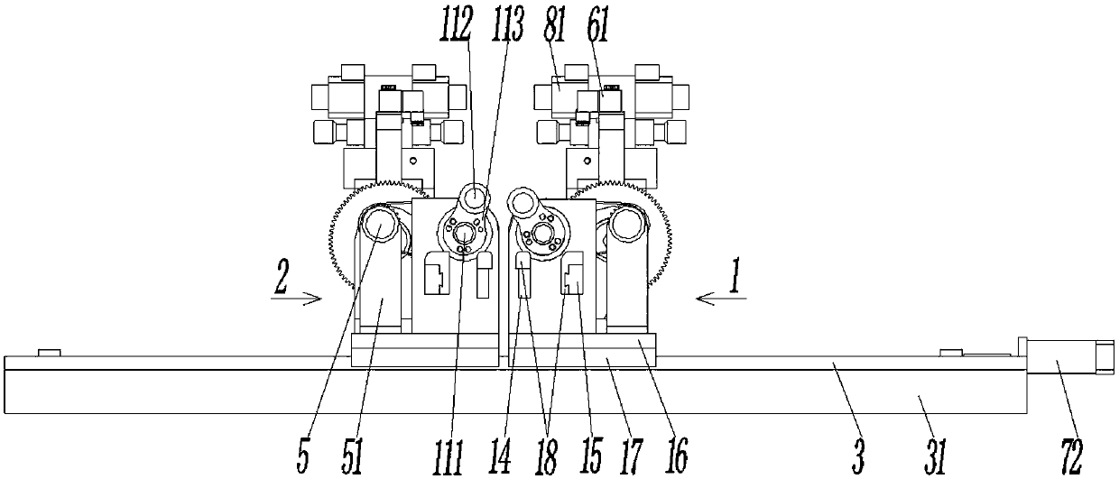
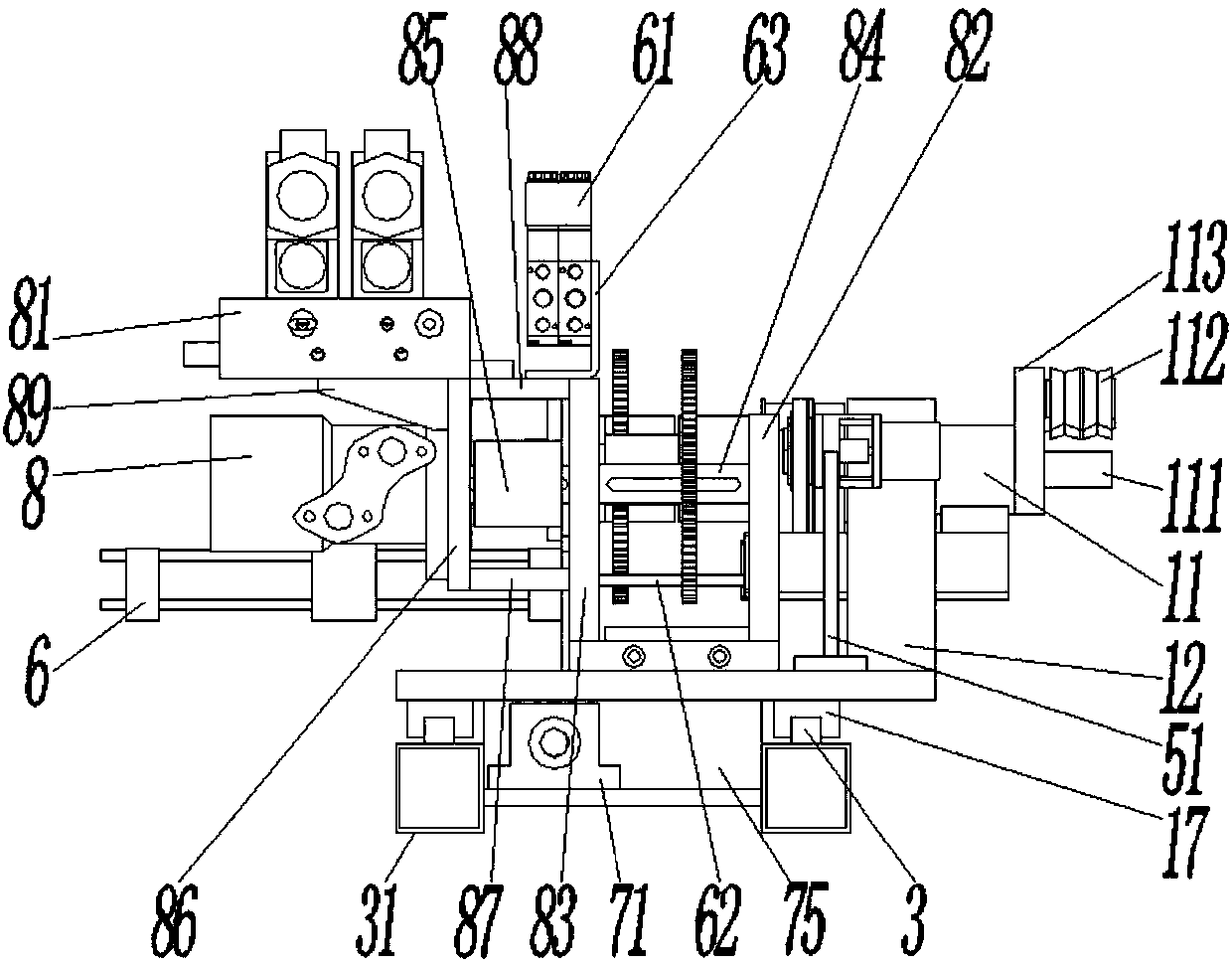
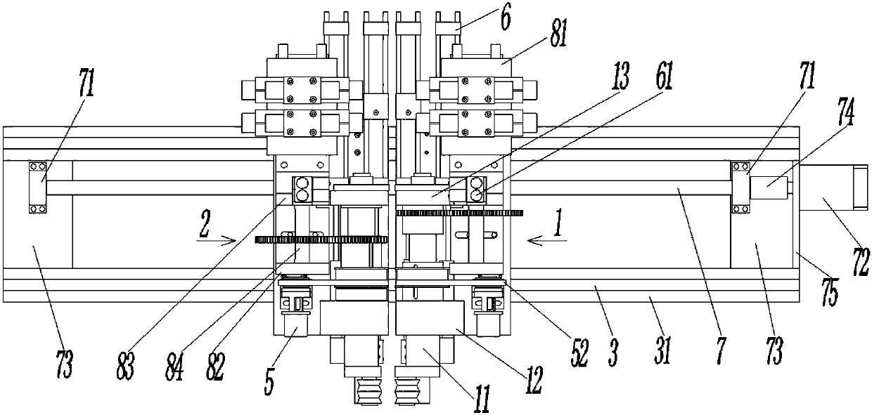
[0041] see Figure 1~4 , an automatic steel bar bending device, including a right bending hoop 1 and a left bending hoop 2 symmetrically arranged on the left and right, the right bending hoop 1 includes a rotating shaft 11; the rotating shaft 11 is rotatably connected to the seat body, and the The seat body includes a front seat body 12 and a rear seat body 13 which are vertically opposite to each other, and the rotating shaft 11 passes through the front seat body 12 and the rear seat body 13 and is rotatably coupled with the front seat body 12 and the rear seat body 13 by bearings; One end of the shaft 11 passing through the front seat body 12 is provided with a torsion core 111 and a torsion head 112, the torsion core 111 is coaxial with the rotation shaft 11, and the torsion head 112 is parallel to the torsion core 11...


PUM


Abstract

The invention relates to an automatic reinforcement bending and hooping device. The automatic reinforcement bending and hooping device comprises a right bending and hooping part; the right bending andhooping part comprises a rotating shaft; the rotating shaft is rotationally connected to a base body; a twisting head and a twisting core coaxial with the rotating shaft are arranged at one end of the rotating shaft; the twisting head is parallel to the twisting core, and is fixedly connected with the twisting core through a twisting head connecting plate; the other end of the rotating shaft is connected with a hydraulic motor; the base body is connected with a primary bending and shaping block and a secondary bending and shaping block capable of sliding in the axial direction of the rotatingshaft; a horizontal chute is formed in the lower surface of the base body; and the base body is erected on a slide rail through the horizontal chute. The automatic reinforcement bending and hooping device further comprises a left bending and hooping part in left-right symmetry with the right bending and hooping part; a lead screw parallel to the slide rail is arranged below the base body; the lead screw consists of two external thread sections with opposite rotating directions; and base bodies of the left bending and hooping part and the right bending and hooping part are connected with the lead screw through screw rings. The automatic reinforcement bending and hooping device effectively prevents the problem of lower efficiency due to multiple times of positioning and bending in bending of square stirrups, and achieves the effects of high bending efficiency, simple and convenient operation and high quality of the formed square stirrups.

Description

technical field [0001] The invention belongs to the technical field of wire rod processing or treatment, and in particular relates to an automatic steel bar bending hoop device. Background technique [0002] In the steel frame structure of a building, in addition to the linear main reinforcement, square stirrups are also required to connect several main reinforcements to form a steel skeleton. The connection between the stirrup and the main reinforcement can be binding or welding. Square stirrups need to be formed by bending straight steel bars, and the way of bending bars has also evolved from manual bending to bending by a hoop bending machine to reduce labor intensity and improve efficiency. The existing hoop bending machine bends steel bars by twisting the core and twisting the head. To obtain a square hoop requires four positioning and bending, and each bending needs to determine the bending point successively. Although the labor intensity is reduced, the efficiency Th...

Claims


Application Information

Patent Timeline
Patent Type & Authority Applications(China)
IPC IPC(8): B21F1/00B21F23/00B21F27/20
CPCB21F1/00B21F23/00B21F27/20
Inventor 刘赫凯杨炬李智能陈刚田达飞
Owner CHINA METALLURGICAL CONSTR ENG GRP
Why Eureka
Try Eureka