
Forced circulation axial flow pump

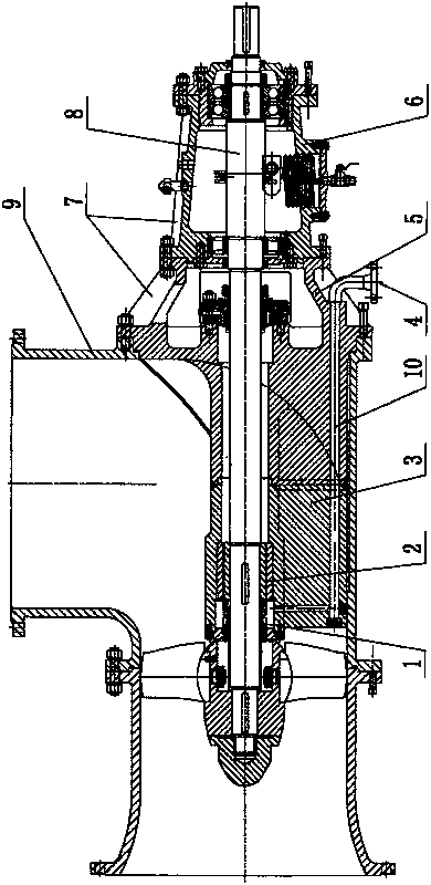
A forced circulation, axial flow pump technology, applied in axial flow pumps, pumps, components of pumping devices for elastic fluids, etc., can solve the problems of troublesome assembly and disassembly, poor operation stability, long axial dimension, etc. To achieve the effect of quick and easy installation, increased rigidity, and protection from wear and corrosion

Inactive Publication Date: 2018-03-16
项达章
View PDF7 Cites 2 Cited by
  • Summary
  • Abstract
  • Description
  • Claims
  • Application Information

AI Technical Summary

Problems solved by technology

[0002] At present, horizontal axial flow pumps are more and more widely used, and their structural characteristics are: the axial dimension is relatively long, and the cantilever of the pump shaft at the end of the impeller is relatively large, resulting in poor overall operation stability of the pump and a short service life of the pump
The connection between the pump cover and the pump body is more complicated, the assembly and disassembly are more troublesome, and the maintenance is not convenient

Method used


Image

  • Forced circulation axial flow pump

Examples


Embodiment Construction

[0012] In the accompanying drawings, the forced circulation axial flow pump of the present invention is mainly composed of a pump body, a pump shaft, an impeller, a pump cover and a bearing body. The pump shaft 8 is supported by the bearing body 6, and the tail end of the pump shaft 8 is equipped with an impeller. ; The end of the pump shaft 8 near the impeller is equipped with a mechanical seal device 1 and a guide bearing 2 in sequence; the guide bearing 2 is located in the support tube 3 and supported by the support tube 3, and the right end of the support tube 3 is welded with the pump cover 5; the support tube is connected to the rotor The components are supported, shortening the cantilever of the pump shaft at the impeller end, increasing the rigidity of the pump shaft, enhancing the stability of the rotor parts, and prolonging the service life of the equipment; the mechanical seal device completely isolates the shaft from the conveying medium, effectively preventing shaft...


PUM


Abstract

Disclosed is a forced circulation axial flow pump. The forced circulation axial flow pump is structurally characterized in that a mechanical sealing device and a guide bearing are installed at the position, close to the impeller end, of a pump shaft in sequence. The guide bearing is located in a supporting pipe. A shaft cantilever is shortened through supporting of the guide bearing for the pump shaft. The stability of a rotor part is enhanced, and the service life of the equipment is prolonged. The mechanical sealing device completely isolates the shaft from a conveying medium. Wear and corrosion of the shaft are effectively prevented, and the maintenance cost of the equipment is reduced. A pump cover, a bearing body and the pump shaft form a whole to be connected with the pump body. Therotor part can be completely pulled out, disassembly, assembly and repair are convenient, and time and effort are saved. Through holes are formed in the pump cover and the supporting pipe and connected with a sealing flush interface, cooling and lubrication functions on the shaft and the guide bearing can be achieved by inputting flushing liquid through the interface, and mechanical breakdown of the rotor part caused by temperature change is reduced. An in-out opening of a pump body is designed into a 90-degree bent head form, the forced circulation axial flow pump can be directly connected toa pipeline, any support is not needed, and installing is fast and convenient.

Description

technical field [0001] The invention relates to the technical field of mechanical engineering pumps, in particular to a forced circulation axial flow pump. Background technique [0002] At present, horizontal axial flow pumps are more and more widely used, and their structural characteristics are: the axial dimension is relatively long, and the cantilever of the pump shaft at the end of the impeller is relatively large, which leads to poor overall operation stability of the pump and shortens the life of the pump. The connection between the pump cover and the pump body is more complicated, the assembly and disassembly are more troublesome, and the maintenance is also inconvenient. Contents of the invention [0003] In order to overcome the deficiencies of the prior art, the object of the present invention is to provide a forced circulation axial flow pump with a reduced cantilever for installing the pump shaft at the impeller end and convenient disassembly and maintenance. ...

Claims


Application Information

Patent Timeline
Patent Type & Authority Applications(China)
IPC IPC(8): F04D3/00F04D29/04F04D29/046F04D29/10F04D29/52F04D29/58F04D29/06
CPCF04D3/005F04D29/04F04D29/046F04D29/061F04D29/106F04D29/528F04D29/586
Inventor 项达章
Owner 项达章
Learn More