Polishing device of motor shaft

A technology of polishing device and motor shaft, applied in the direction of grinding drive device, surface-polished machine tool, grinding machine parts, etc. Improve polishing efficiency and polishing quality, save labor, and avoid polishing effects

Inactive Publication Date: 2018-03-20
苏州市润达机械制造有限公司
View PDF0 Cites 2 Cited by
  • Summary
  • Abstract
  • Description
  • Claims
  • Application Information

AI Technical Summary

Problems solved by technology

[0003] The polishing operation of the existing motor shaft is mostly performed manually through the polishing wheel on the outer surface of the shaft. During the polishing process, the motor shaft needs to be taken off from the polishing machine, which not only reduces the production efficiency, but also increases the workload. The working intensity of personnel may also cause secondary damage to the shaft, which brings a lot of inconvenience to the actual production and processing

Method used


Image

  • Polishing device of motor shaft
  • Polishing device of motor shaft
  • Polishing device of motor shaft

Examples


Embodiment Construction

[0016] The present invention will be further described in detail below in conjunction with the accompanying drawings and specific embodiments.

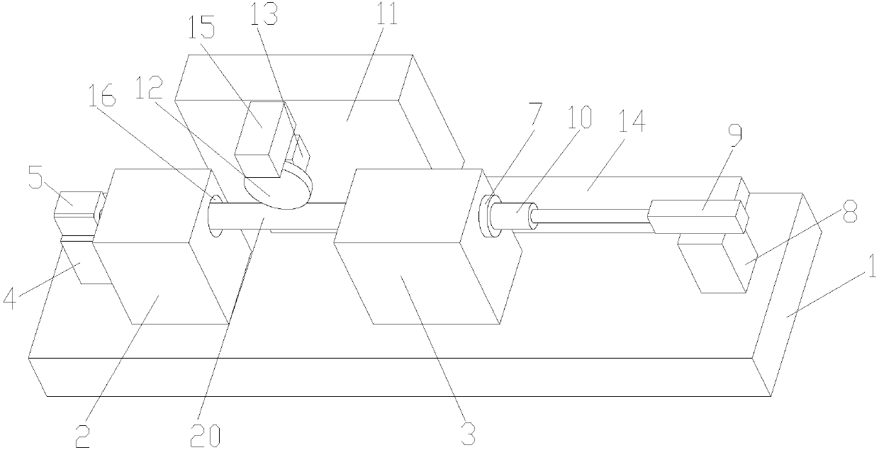
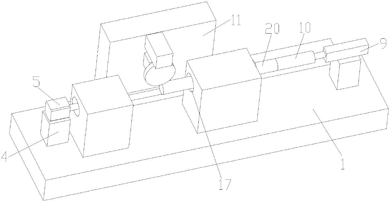
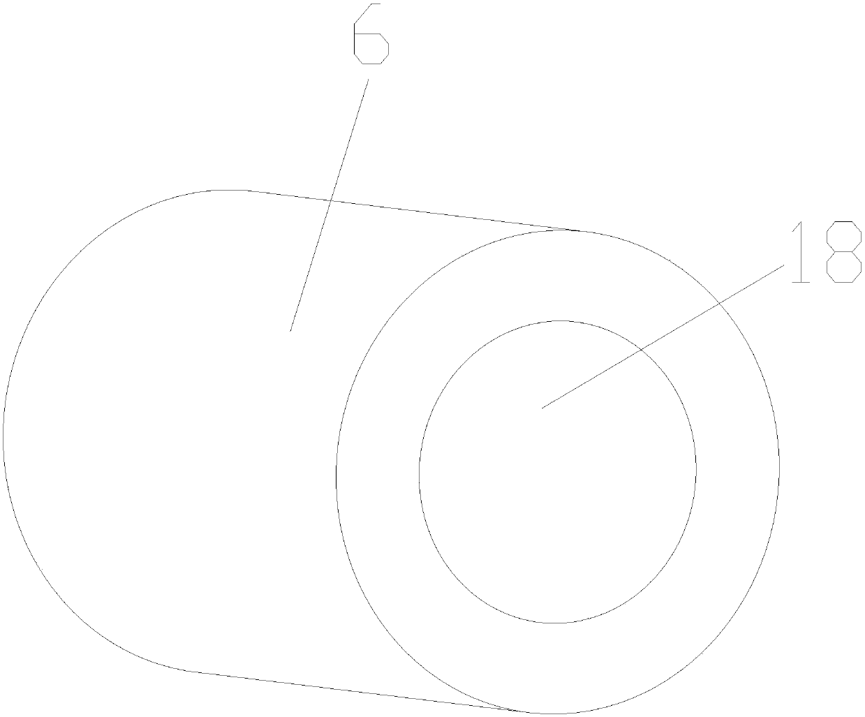
[0017] as attached Figure 1-3 The shown polishing device of a motor shaft according to the present invention includes a base 1, a left positioning block 2, a right positioning block 3, a motor seat 4, a motor 5, a left cylindrical block 6, a fixing cylinder 7, and a cylinder seat 8 , Telescopic cylinder 9, electromagnet block 10, substrate 11 and polishing assembly; The base 1 is provided with a left positioning block 2 and a right positioning block 3; Positioning hole 16 and right positioning hole 17, and above-mentioned two positioning holes are located on the same axis line; One side of described left positioning block 2 is provided with the motor 5 that is positioned on motor seat 4; One side of the rotating shaft of described motor 5 A left cylindrical block 6 positioned in the left positioning hole 16 is provided, and a housin...


PUM


Abstract

The invention relates to a polishing device for a motor shaft. A left positioning block and a right positioning block are arranged on a base; a left positioning hole and a right positioning hole are respectively opened on the left positioning block and the right positioning block, and the above two positioning holes are located at On the same axis; one side of the left positioning block is provided with a motor on the motor base; one side of the motor shaft is provided with a left cylindrical block located in the left positioning hole, and the left cylindrical block has a receiving groove; the right positioning block There is a fixed cylinder in the hole, and the inner diameter of the fixed cylinder is the same as the diameter of the motor shaft; the materials of the left cylindrical block and the fixed cylinder are electromagnets; there is a telescopic cylinder on the side of the right positioning block; There is an electromagnet block inside; a slidable substrate is provided between the left positioning block and the right positioning block; a polishing assembly that can be lifted up and down is provided on the substrate. , save labor, improve polishing efficiency and polishing quality.

Description

technical field [0001] The invention relates to a polishing device, in particular to a polishing device for a motor shaft. Background technique [0002] The motor shaft is an important part of the motor. After it is produced, it is inevitable that there will be edges and corners on the end surface, and the combination will inevitably have some burrs, and the motor shaft is a shaft with high precision requirements. Class parts, so they need to be polished. [0003] The polishing operation of the existing motor shaft is mostly performed manually through the polishing wheel on the outer surface of the shaft. During the polishing process, the motor shaft needs to be taken off from the polishing machine, which not only reduces the production efficiency, but also increases the workload. The working intensity of the personnel may also cause secondary damage to the shaft, which brings a lot of inconvenience to the actual production and processing. Contents of the invention [00...

Claims


Application Information

Patent Timeline
Patent Type & Authority Applications(China)
IPC IPC(8): B24B29/04B24B41/06B24B47/20
CPCB24B29/04B24B41/06B24B47/20
Inventor 顾龙元方国士缪惠明
Owner 苏州市润达机械制造有限公司
Why Eureka
Try Eureka