Laser cleaning device for inductor pins

A technology for laser cleaning and pins, which is applied in the direction of cleaning methods and appliances, chemical instruments and methods, etc., can solve the problems of inapplicability, residual paint layer on the side of pins, high defect rate, etc., so as to improve processing efficiency and reduce unit cost , the effect of simple structure

A technology for laser cleaning and pins, which is applied in the direction of cleaning methods and appliances, chemical instruments and methods, etc., can solve the problems of inapplicability, residual paint layer on the side of pins, high defect rate, etc., so as to improve processing efficiency and reduce unit cost , the effect of simple structure

CN105032849AActive Publication Date: 2015-11-11武汉拓尔奇光电技术有限公司

Image

  • Laser cleaning device for inductor pins
  • Laser cleaning device for inductor pins

Examples


Embodiment

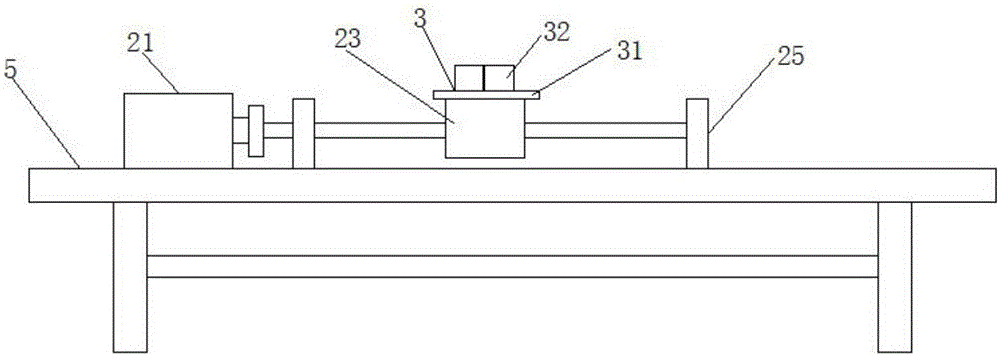
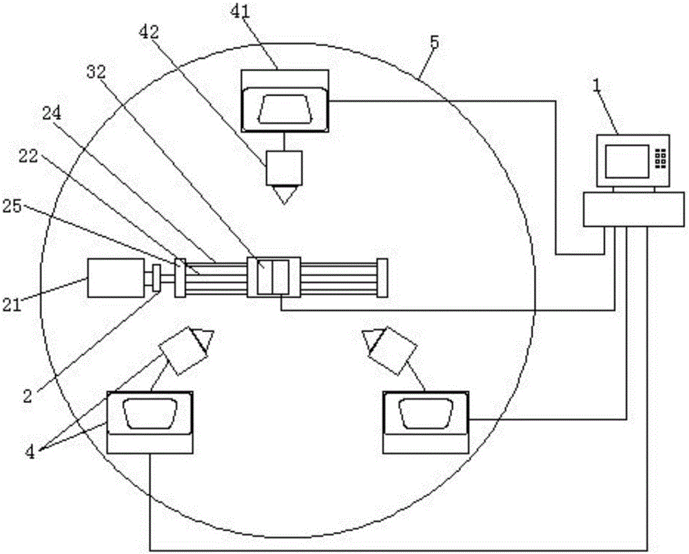
[0017] Example: such as Figures 1 to 2 As shown, the inductance pin laser cleaning equipment of the present invention includes an industrial computer 1, a telescopic transmission mechanism 2, a clamp tray mechanism 3, 3 laser generator assemblies 4 and a workbench 5, and the above-mentioned telescopic transmission mechanism 2 is installed on the workbench 5 , and connect the above-mentioned industrial computer 1 through the line, the above-mentioned clamp tray mechanism 3 is fixed on the telescopic transmission mechanism 2, and connect the above-mentioned industrial computer 1 through the line, and the three above-mentioned laser generator assemblies 4 are all installed on the workbench 1;

[0018] Above-mentioned laser generator assembly 4 comprises laser generator 41 and the laser vibrating mirror 42 that is connected with laser generator 41, and above-mentioned laser generator 41 connects above-mentioned industrial computer 1 by line, and the laser vibrating mirror 42 of 3 ...


PUM


Abstract

A laser cleaning device for inductor pins comprises an industrial personal computer, a flexible transmission mechanism, a clamp tray mechanism, three laser emitter assemblies and a workbench, wherein the flexible transmission mechanism is installed on the workbench and connected with the industrial personal computer through a line; the clamp tray mechanism is fixed to the flexible transmission mechanism and connected with the industrial personal computer through a line; the three laser emitter assemblies are installed on the workbench; each laser emitter assembly comprises a laser generator and a laser galvanometer connected with the laser generator; the laser generators are connected with the industrial personal computer through lines; the laser galvanometers of the three laser emitter assemblies are evenly distributed on the same horizontal plane and are all used in cooperation with an electromagnetic clamp. The laser cleaning device for inductor pins has the beneficial effects that the structure is simple, use is convenient, manpower and material resource are saved, and the machining efficiency is improved; the unit cost for cleaning of pins of electronic elements is dramatically reduced, and the requirements of people for production and machining are met.

Description

technical field [0001] The invention relates to a laser cleaning device for inductor pins, which belongs to the technical field of laser manufacturing applications, and in particular to laser cleaning equipment for inductor pins. Background technique [0002] At present, in terms of the production of discrete electronic components, electronic components have gradually developed towards the direction of miniaturization and solid packaging. In this way, the pins of electronic components will be smaller and thinner than before. In the new process manufacturing process, the surface paint layer must be removed from the pins of discrete electronic components such as inductor pins, so as to facilitate the implementation of the subsequent soldering process. [0003] Due to the requirements of the process, the surface paint layer must be completely removed, otherwise it will cause poor contact, but the pins cannot be damaged. At present, it is mainly carried out manually, and chemic...

Claims


Application Information

Patent Timeline
11 Nov 2015
Publication
CN105032849A
IPC
B08B7/00
CPC
B08B7/0042
Inventors
范陈杰; 吴华